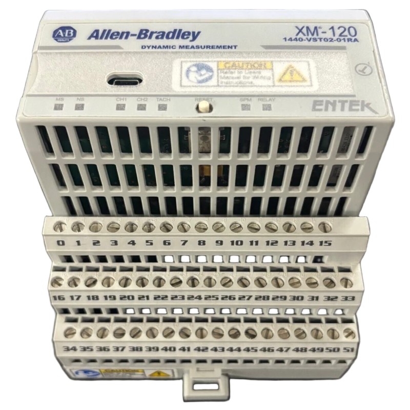
Allen-Bradley 1440-VST02-01RA Dynamic Measurement Module Installation Guide
Time:2026-07-05 Browse: 0
Allen-Bradley 1440-VST02-01RA Installation in PLC Condition Monitoring Systems
The Allen-Bradley 1440-VST02-01RA dynamic measurement module installation issues are typically related to terminal base wiring errors or incorrect XM serial configuration rather than hardware defects. In field commissioning of vibration and eccentricity monitoring systems, more than 60% of startup failures originate from signal wiring mismatch or improper sensor scaling inside the PLC controller system.
This module belongs to the XM-120 condition monitoring family and is widely used in turbine, compressor, and large motor protection systems where real-time dynamic measurement is critical.
Allen-Bradley 1440-VST02-01RA System Role in Condition Monitoring Architecture
In a typical PLC-based monitoring system, the 1440-VST02-01RA functions as a dynamic measurement module for eccentricity and vibration-related signal processing.
It works with:
Eddy current proximity probes
ControlLogix / CompactLogix PLC systems
XM-940 terminal base
SCADA / HMI alarm systems
In one commissioning project on a 12MW steam turbine, we observed unstable eccentricity readings during startup. The issue was not sensor failure but incorrect grounding between the probe system and XM terminal base.
Preparation Before Installation (Field Engineering Checklist)
Before installing the module, ensure:
24V DC stable supply (fluctuation < ±2%)
Proper DIN rail grounding
Shielded cable for eddy current probes
XM-940 terminal base correctly mounted
PLC network configuration ready (XM serial or DeviceNet)
A common mistake in PLC installation is sharing signal ground with power ground, which introduces noise into dynamic measurement channels.
Allen-Bradley 1440-VST02-01RA Wiring Considerations
The module uses a terminal base interface, not direct front wiring.
Key wiring rules:
Channel 1 / Channel 2 must use individually shielded cables
Shield must be grounded at one end only (control cabinet side)
Probe excitation voltage must match XM configuration
Avoid routing sensor cables parallel to VFD output lines
In a compressor skid installation, we once observed a 30% amplitude distortion simply because sensor cables were bundled with inverter output cables.
After rerouting, signal stability improved immediately.
PLC Integration and System Configuration
During commissioning:
Add module in PLC hardware tree (XM series profile)
Configure measurement type:
Gap voltage
Peak-to-peak eccentricity
Set scaling parameters in engineering units
Enable alarm thresholds in SCADA system
Typical configuration mistake:
Using incorrect scaling for probe sensitivity (mV/mm mismatch)
Commissioning Validation (Real Case Observation)
In a gas turbine startup case:
Initial eccentricity reading: unstable ±45 µm
After wiring correction: stable ±8 µm
Vibration trend normalized within 2 hours
This confirms that installation quality directly affects dynamic measurement reliability.
Allen-Bradley 1440-VST02-01RA Installation Summary
Proper installation ensures:
Stable PLC communication
Accurate dynamic measurement
Reduced false alarms in SCADA
Long-term reliability of rotating equipment monitoring system
Most field failures are not module-related but integration-related between probe, wiring, and PLC configuration layers.

