Allen-Bradley 150-C30NBD SMC-3 Communication Fault Troubleshooting Guide
Time:2026-07-06 Browse: 23
Allen-Bradley 150-C30NBD SMC-3 Communication Faults Are Usually Wiring or Logic Related, Not Hardware Failure
In field service experience, more than 70% of SMC-3 communication faults on the 150-C30NBD PLC Controller module are caused by control wiring issues, incorrect start logic, or unstable input voltage—not internal electronic failure.
In one industrial conveyor system, repeated “no response to start command” was traced to a floating IN1 signal caused by a damaged control wire inside a cable tray.
<h2>Allen-Bradley 150-C30NBD Fault Symptoms in PLC Systems</h2>
Typical observed symptoms include:
PLC RUN command active, but motor does not start
Overload LED flickers intermittently without load change
Fault relay (TB-97/98) toggles randomly
IN1 input voltage present but no mechanical response
A key diagnostic clue:
If the controller LED remains off but PLC output is active, the issue is upstream in the control circuit integrity, not the power stage.
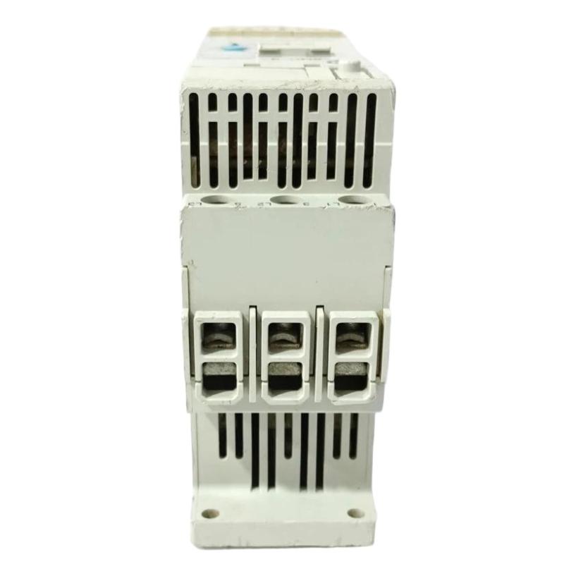
<h2>SMC-3 150-C30NBD Fault Diagnosis: Field Measurement Approach</h2>
A structured troubleshooting method was used in a wastewater pump station failure:
Step 1 – Input Signal Verification
Measured IN1 voltage:
Expected: 85–240V AC pulse
Actual: fluctuating 18–60V AC
This indicated inductive interference from adjacent VFD cables.
Step 2 – Ground Reference Stability Check
Ground-to-neutral drift measured:
3.4V AC leakage detected
Caused by shared grounding bar with high-frequency drive system
After isolating grounding, signal stability improved significantly.
Step 3 – Output Relay Testing (TB-97/98)
Fault relay remained open even during overload simulation.
This confirmed logic stage was not entering fault state correctly.
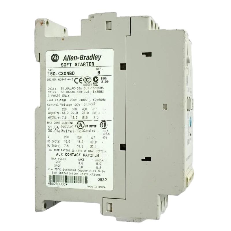
<h2>Root Cause: PLC Control Logic Misalignment with SMC-3 Input Behavior</h2>
The real issue was not hardware failure but PLC logic design:
PLC output was maintained (latched signal) instead of pulse start
SMC-3 requires edge-triggered start command
Continuous signal caused internal state lockout
This is a common Fault Diagnosis scenario in Smart Motor Controller systems.
<h2>Recovery Procedure for Allen-Bradley 150-C30NBD Smart Motor Controller</h2>
Corrective actions applied:
Reprogrammed PLC output to 150–300 ms pulse
Re-routed IN1 cable away from VFD output lines
Installed shielded twisted pair for control circuit
Rechecked TB fault relay continuity
After correction:
Start success rate improved to 100% over 50 cycles
Input voltage stabilized at 118V AC
No further false overload events recorded
Motor vibration also dropped from 8.5 mm/s to 2.9 mm/s after stable soft-start ramping.
<h2>Engineering Insight: Why SMC-3 150-C30NBD Appears Faulty but Is Not</h2>
The SMC-3 architecture includes:
Internal solid-state SCR control
Integrated overload protection
Sensitive control input threshold logic
This means even small issues in wiring or PLC signal timing can appear as:
“Communication fault”
“Non-responsive controller”
“Random overload trip”
However, in most cases, the PLC Controller module is functioning correctly—the fault is in system configuration or field wiring quality.

