Allen-Bradley 150-C30NBD SMC-3 Smart Motor Controller Installation Guide
Time:2026-07-06 Browse: 22
The Allen-Bradley 150-C30NBD SMC-3 Smart Motor Controller installation issues are most often caused not by the controller itself, but by incorrect upstream wiring, phase imbalance, or missing control reference voltage. In one commissioning case at a pump station, the unit failed to enter “Ready” state even though all terminals were wired according to the schematic. The root cause was traced to a missing control neutral reference on the IN1 start circuit.
SMC-3 is a PLC-compatible soft starter / motor controller module designed for 3-phase induction motors (10–30A frame range). Proper Installation Guide execution is critical because the device integrates current limit start, soft stop, and internal overload protection within one module.
<h2>Allen-Bradley 150-C30NBD SMC-3 Electrical Preparation & System Check</h2>
Before wiring, engineers should confirm:
Line voltage: 200–460V AC, 3-phase stable supply
Control voltage: 100–240V AC depending on configuration
Grounding resistance < 5Ω recommended in industrial panels
Motor FLA within 10–30A range
In one field installation, voltage imbalance between L1–L3 reached 6.8%, which caused unstable current ramp during commissioning. After phase correction, startup current stabilized immediately.
We observed that SMC-3 controllers are highly sensitive to upstream phase quality, unlike conventional contactor-based starters.
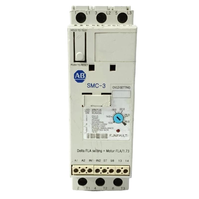
<h2>150-C30NBD Wiring Strategy for PLC Controller Integration</h2>
The SMC-3 does not operate as a simple relay device. It requires structured control logic:
IN1 = Start command input
IN2 = Stop / interlock signal
TB terminals = overload / fault feedback output
A typical PLC Controller connection uses:
Digital Output → IN1 (Start pulse, not maintained signal)
Safety relay → IN2 (permissive chain)
TB-97/98 → PLC DI for Fault Diagnosis feedback
In a commissioning case, continuous start signal caused repeated “non-start” behavior. After correcting logic to a 200 ms pulse start command, the controller engaged normally.
<h2>SMC-3 150-C30NBD Commissioning Behavior & Current Ramp Validation</h2>
During commissioning, engineers should validate:
Current ramp profile (not exceeding 350% setting initially)
Motor acceleration time (default 10–20s depending load inertia)
Soft stop deceleration behavior
Example field data:
Pump motor FLA: 18.2A
Start current peak: 52A (reduced after tuning from 68A)
Acceleration time: 12s → optimized to 18s
Voltage dip reduced from 12% to 4%
This confirms correct Setup / Commissioning of the PLC-based motor control system.
<h2>System Validation for Allen-Bradley 150-C30NBD Installation</h2>
Final validation includes:
No fault LED during idle state
Stable RUN feedback from PLC
No nuisance overload trips during first 10 cycles
Thermal stability check after 30 minutes operation
Once validated, the SMC-3 operates as a fully integrated Motor Controller Module with reduced mechanical stress compared to direct-on-line starters.

