Allen Bradley 150-F135NBD SMC Flex Soft Starter Installation Guide
Time:2026-07-09 Browse: 20
Allen Bradley 150-F135NBD SMC Flex Soft Starter Installation Overview
The Allen Bradley 150-F135NBD SMC Flex Soft Starter installation process requires accurate motor parameter setup, correct power wiring, and systematic commissioning checks to ensure reliable motor starting performance. In industrial applications, startup instability is usually caused by incorrect configuration, wiring mistakes, or unsuitable acceleration settings rather than a defective soft starter.
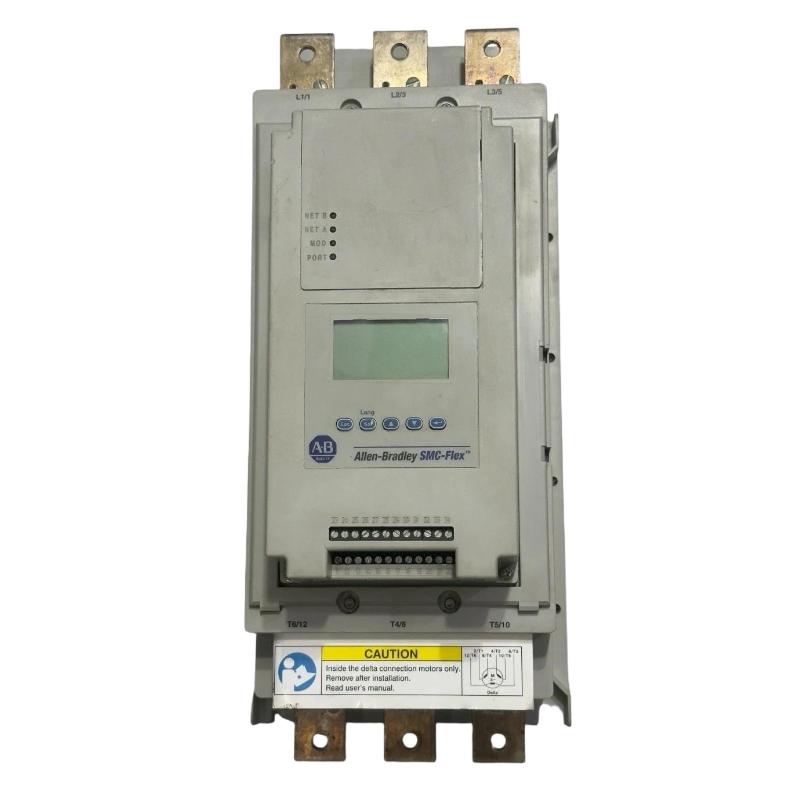
The Allen Bradley 150-F135NBD is a 135 A solid-state motor controller designed for controlling three-phase induction motors in applications such as pumps, fans, compressors, and conveyors. As part of an automation system, it is commonly connected with a PLC Controller for automatic start/stop control, fault monitoring, and production sequence management.
During a commissioning project for a cooling water pump system, engineers installed an Allen Bradley 150-F135NBD SMC Flex Soft Starter in a motor control cabinet. The motor initially showed a long acceleration time and occasional startup interruption. Field inspection found that the programmed motor current value did not match the actual motor nameplate rating. After correcting the System Configuration parameters, the motor reached stable operation within the expected acceleration period.
Allen Bradley 150-F135NBD Soft Starter Installation Preparation and System Configuration
Before beginning the Installation Guide procedure, engineers should verify the complete motor control environment.
Important preparation items include:
Confirming motor voltage and rated current
Checking incoming three-phase power quality
Reviewing motor application load characteristics
Preparing control wiring drawings
Confirming PLC Controller I/O requirements
Checking enclosure cooling conditions
The Allen Bradley 150-F135NBD should be selected according to motor full-load current rather than only motor power rating. Different mechanical loads require different starting profiles. A lightly loaded fan and a high-inertia conveyor may use similar motors but require different Setup parameters.
A practical commissioning approach is to record the motor nameplate data before powering the unit. Incorrect motor data can affect current regulation, overload protection, and Fault Diagnosis accuracy.
Allen Bradley 150-F135NBD Power Wiring Installation Procedure
Correct power wiring is critical for stable operation of the SMC Flex Soft Starter.
The main electrical connections normally include:
Three-phase incoming power connection
Motor output connection
Ground protection connection
Control power wiring
Before energizing the Allen Bradley 150-F135NBD, technicians should perform electrical verification:
Measure line voltage between phases
Check phase sequence
Confirm cable insulation condition
Verify terminal tightening torque
In one field installation, the soft starter displayed unstable current readings during startup. The incoming voltage was measured at 460 VAC and appeared normal. However, current analysis showed:
Phase A: 142 A
Phase B: 118 A
Phase C: 140 A
The imbalance indicated a connection issue rather than a controller failure. Inspection revealed a loose motor terminal connection. After correction, phase current difference was reduced below 3%.
Allen Bradley 150-F135NBD Control Wiring and PLC Controller Integration Setup
The Allen Bradley 150-F135NBD is frequently integrated into PLC-based automation systems.
Typical control signals include:
Motor start command
Stop command
Running feedback
Fault output
Reset signal
During Setup and Commissioning, engineers should verify the complete signal chain:
PLC output → SMC Flex input → Motor operation → Feedback signal → PLC monitoring
A common mistake during installation is connecting the soft starter directly into the automation sequence before confirming standalone operation.
The recommended engineering method is:
First, test local operation.
Second, confirm motor acceleration performance.
Third, connect PLC Controller logic.
Finally, validate automatic operation.
This approach makes future Troubleshooting easier because it separates hardware problems from PLC programming issues.
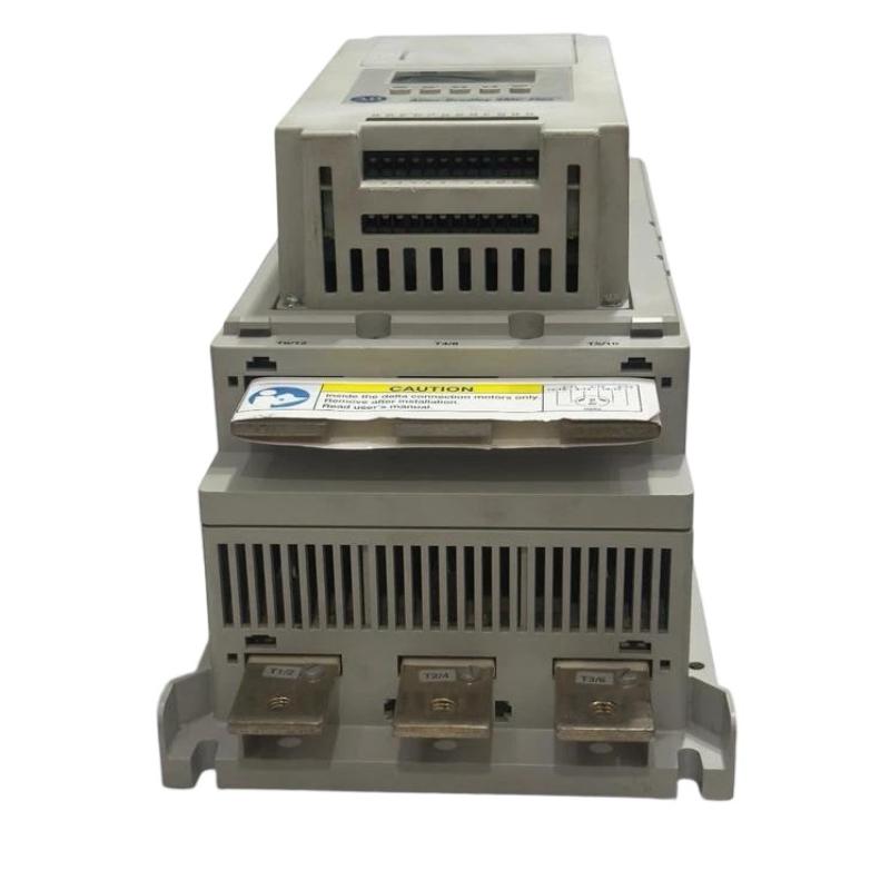
Allen Bradley 150-F135NBD SMC Flex Commissioning Test and Validation
The final commissioning stage should include operational testing under real load conditions.
Key validation points include:
Starting current measurement
Acceleration time verification
Overload parameter checking
Fault history review
PLC feedback confirmation
Example commissioning data:
Motor voltage: 460 VAC
Motor current: 125 A
Starting current: 300% FLC
Acceleration time: 10 seconds
After completing the Installation Guide process, the Allen Bradley 150-F135NBD SMC Flex Soft Starter should provide smooth acceleration, reduced mechanical shock, and reliable motor protection.

