Allen Bradley 150-F85NBDB SMC Flex Smart Motor Controller Installation Guide
Time:2026-07-10 Browse: 20
Overview of Allen Bradley 150-F85NBDB SMC Flex Installation Requirements
The Allen Bradley 150-F85NBDB SMC Flex Smart Motor Controller installation process requires accurate electrical design, proper motor parameter setup, and complete commissioning checks to achieve stable soft starting performance. In industrial motor control systems, startup failures are often caused by incorrect wiring, unsuitable configuration settings, or incomplete PLC integration rather than controller hardware problems.
The 150-F85NBDB is an 85 A solid-state motor controller designed for three-phase motor applications where controlled acceleration, reduced mechanical stress, and motor protection are required. It is commonly applied in pumps, fans, conveyors, compressors, and other industrial drive systems.
During one conveyor system commissioning project, engineers installed an SMC Flex controller to replace a traditional starter. The motor was able to run, but excessive current spikes appeared during acceleration. Field measurements showed the starting current reached 390% of motor full-load current. After reviewing the motor data and adjusting the acceleration parameters, the current peak was reduced to 270%, improving both motor stability and mechanical performance.
Allen Bradley 150-F85NBDB Motor Controller Installation Preparation
Before installing the Allen Bradley 150-F85NBDB PLC Controller system, engineers should verify the complete application conditions, including electrical requirements and mechanical load characteristics.
Important preparation points include:
Confirming motor voltage and rated current
Checking controller current capacity
Reviewing incoming power quality
Selecting suitable cable specifications
Confirming cabinet installation space
Verifying cooling and ventilation conditions
Checking PLC control requirements
The motor application has a direct influence on SMC Flex performance. A pump with high inertia requires different acceleration settings compared with a lightly loaded fan system. Incorrect assumptions during preparation may lead to unnecessary overload alarms or unstable starting behavior.
A field engineer should also confirm whether the existing control system requires remote commands, status feedback, or integration with a PLC Controller before completing the wiring design.
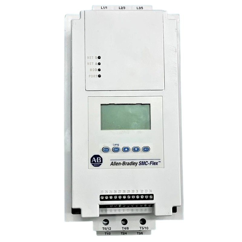
Allen Bradley 150-F85NBDB Wiring and System Configuration Setup
The Allen Bradley 150-F85NBDB Installation Guide must focus on correct power and control circuit connections because wiring errors are one of the most common causes of commissioning problems.
The installation should verify:
Three-phase incoming power terminals
Motor output connections
Grounding connection
Control power supply
Start and stop inputs
Auxiliary status contacts
External protection circuits
For PLC-based applications, the SMC Flex Module should be configured according to the machine control strategy. The PLC Controller sends operating commands, while the SMC Flex manages motor acceleration, protection functions, and operating feedback.
During a factory installation, engineers found that the motor wiring was correct but the start command could not activate the controller. Electrical testing confirmed that the PLC output signal was available, but the external stop circuit remained open. After correcting the interlock wiring, the controller completed the startup sequence normally.
Allen Bradley 150-F85NBDB Setup and Commissioning Procedure
The Allen Bradley 150-F85NBDB Setup and Commissioning process requires parameter verification based on the actual motor and application conditions.
Key commissioning parameters include:
Motor full-load current setting
Acceleration ramp time
Initial torque adjustment
Overload protection configuration
Stop mode selection
Input control settings
During commissioning, engineers should monitor:
Motor starting current
Acceleration smoothness
Controller fault records
Motor vibration
Feedback signal response
In one real commissioning case, a motor-driven pump showed unstable acceleration after installation.
Initial measurements:
Starting current: 360% FLA
Acceleration time: 22 seconds
Vibration level: 6.8 mm/s
After adjusting the SMC Flex configuration:
Starting current: 250% FLA
Acceleration time: 14 seconds
Vibration level: 3.2 mm/s
The adjustment improved motor startup performance and reduced mechanical impact on the pump system.
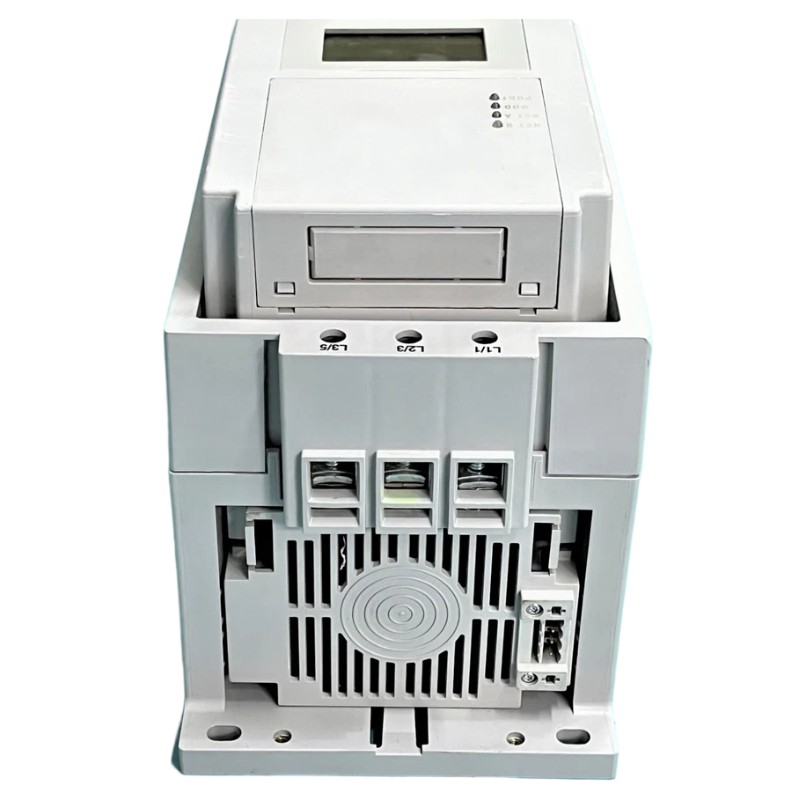
Allen Bradley 150-F85NBDB Installation Validation and Field Testing
After completing commissioning, the Allen Bradley 150-F85NBDB Smart Motor Controller should undergo final operational verification.
The final inspection should include:
Checking terminal connections
Confirming motor rotation direction
Testing start and stop commands
Reviewing fault history
Confirming PLC feedback signals
Recording normal operating current
The controller should operate as part of a complete motor control system. Reliable performance depends on the correct interaction between the SMC Flex Controller, PLC Controller, motor, and field devices.
Proper Installation Guide practices reduce future Troubleshooting requirements and improve long-term equipment availability.

