Allen Bradley 1606-XL480E-3 Power Supply Installation Guide for Industrial Control System Commission
Time:2026-07-27 Browse: 30
Industrial control panel failures involving the Allen Bradley 1606-XL480E-3 Power Supply are frequently traced to incorrect wiring, poor grounding, or insufficient ventilation rather than defects in the power supply itself. A systematic Installation Guide and Commissioning procedure helps ensure stable 24 VDC output and reliable operation of PLC controllers, I/O modules, HMIs, and communication devices.
Allen Bradley 1606-XL480E-3 Power Supply Role in System Configuration
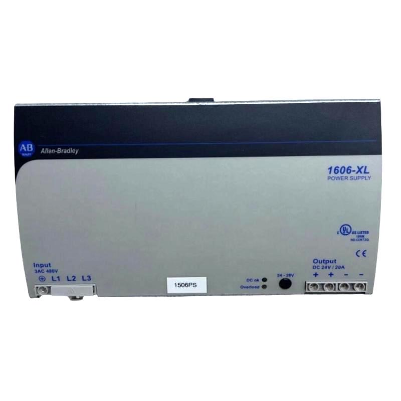
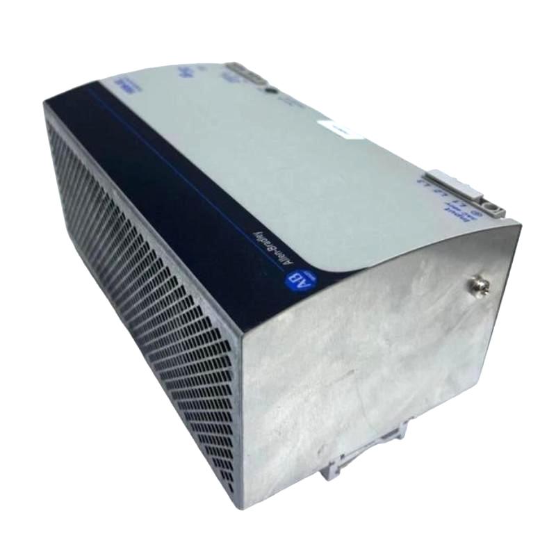
The Allen Bradley 1606-XL480E-3 is a DIN rail-mounted industrial power supply designed to convert three-phase AC power into a regulated 24 VDC output for automation equipment. It provides stable DC power for PLC systems, remote I/O stations, industrial networking devices, and field instruments operating in demanding industrial environments.
A properly designed System Configuration should also account for cable length, total load current, and future capacity expansion to maintain long-term power stability.
Allen Bradley 1606-XL480E-3 Installation Preparation
Before installation, experienced engineers normally verify several field conditions rather than installing the unit immediately.
Recommended checks include:
Confirm the incoming three-phase voltage matches the project specification.
Measure cabinet temperature before energizing.
Verify DIN rail grounding continuity.
Reserve adequate clearance above and below the power supply for airflow.
Separate power cables from communication wiring to minimize electrical interference.
In many retrofit projects, poor cabinet ventilation has a greater impact on reliability than the power supply itself.
Allen Bradley 1606-XL480E-3 Wiring and Setup Considerations
During Setup, input and output wiring should be completed carefully.
Typical wiring recommendations include:
Tighten all terminal connections to the specified torque.
Keep DC output cables as short as practical.
Use properly sized conductors for high-current loads.
Connect protective earth before applying input voltage.
Verify output polarity before energizing downstream equipment.
After completing the wiring, measure the unloaded output voltage. A stable reading close to 24 VDC confirms that the initial installation is ready for Commissioning.
Allen Bradley 1606-XL480E-3 Commissioning Validation
Commissioning should include more than confirming that the POWER indicator is illuminated.
Field engineers generally verify:
Input voltage stability
Output voltage under full load
DC voltage ripple
Cabinet temperature rise
PLC startup sequence
HMI boot time
Network communication status
Only after all connected devices remain stable during continuous operation should the installation be considered complete.
Real Commissioning Experience with Allen Bradley 1606-XL480E-3
During the commissioning of an automotive conveyor system, a PLC unexpectedly restarted several times each day.
Initial inspection suggested a controller fault, but voltage measurements revealed the DC output periodically dropped from 24.1 VDC to approximately 21.8 VDC whenever multiple contactors energized simultaneously.
Further investigation showed that two output terminals had not been fully tightened during installation.
After correcting the wiring and repeating the Commissioning test, the output stabilized at 24.0 VDC, and the production line operated continuously for over 120 hours without another interruption.
This case illustrates that proper installation practices often eliminate issues that appear to be controller failures.

