Allen Bradley 1606-XL480EP Power Supply Installation Guide
Time:2026-07-29 Browse: 9
Overview of Allen Bradley 1606-XL480EP Power Supply Installation
The Allen Bradley 1606-XL480EP power supply installation process requires correct input wiring, load calculation, grounding, and commissioning checks to ensure stable 24V DC power delivery in industrial control systems. This DIN rail power supply is commonly installed in PLC panels, machine automation cabinets, and distributed control applications where reliable DC power is critical.
During field installation, most commissioning issues are not caused by the power supply itself. Incorrect terminal wiring, insufficient protection devices, and poor cabinet grounding are more common reasons for unstable operation.
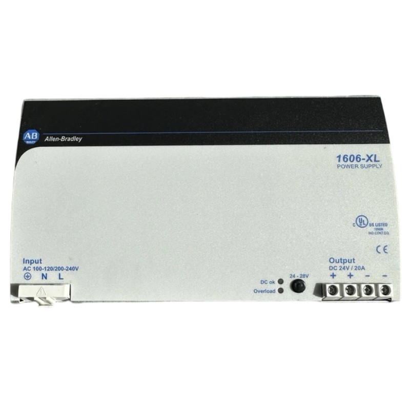
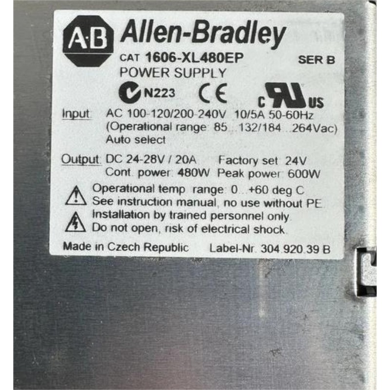
The 1606-XL480EP is designed as an industrial AC/DC power supply used for supplying PLC controllers, I/O modules, sensors, relays, and other automation devices. A proper Installation Guide should consider both electrical parameters and the actual operating environment inside the control cabinet.
Allen Bradley 1606-XL480EP Power Supply Technical Role in Control Systems
In an industrial automation system, the power supply acts as the energy foundation for the entire control network. A voltage fluctuation at the DC output can affect PLC Controller performance, communication modules, and field sensors.
Typical applications include:
PLC control cabinets
Machine automation systems
Remote I/O stations
Industrial monitoring equipment
Motor control panels
The 1606-XL480EP provides regulated DC power for connected devices. Before installation, engineers should confirm the total load current and reserve capacity.
For example:
A control cabinet contained:
PLC Controller: 3.5 A
Communication Module: 1.2 A
Sensor network: 2.0 A
Relay outputs: 1.5 A
The calculated load was 8.2 A. The commissioning engineer maintained additional capacity instead of operating the power supply continuously near maximum output.
Allen Bradley 1606-XL480EP Setup Preparation Before Installation
A successful setup starts before the unit is mounted on the DIN rail.
Field engineers normally check:
AC input voltage compatibility
DC output voltage requirements
Cabinet ventilation
Protective circuit design
Cable size selection
Ground connection quality
The installation environment should avoid excessive heat sources. In one commissioning case, a 1606-XL480EP installed near a braking resistor showed intermittent shutdown after several hours of operation. Temperature measurement showed the cabinet internal temperature exceeded the recommended operating range. After improving airflow, the power supply operated normally.
Allen Bradley 1606-XL480EP Wiring and Electrical Connection Procedure
Correct wiring is essential for reliable operation.
The typical wiring inspection includes:
AC Input Connection
Verify:
Line and neutral connection
Protective earth connection
Proper fuse or circuit breaker protection
Loose input terminals can create voltage drops and generate heat during continuous operation.
DC Output Wiring
The DC output should be connected with suitable cable sizing based on current demand.
Engineers should check:
Positive and negative polarity
Terminal tightening torque
Voltage drop across long cables
A practical field measurement method is:
Measure DC voltage directly at the power supply output.
Measure voltage at the PLC input terminals.
Compare the difference.
For example:
Output terminal voltage: 24.2 VDC
PLC terminal voltage: 23.6 VDC
A 0.6 VDC drop may indicate cable resistance or overloaded wiring.
Allen Bradley 1606-XL480EP PLC System Commissioning Verification
The commissioning phase confirms that the power supply works correctly with the complete automation system.
Engineers usually verify:
Stable DC output voltage
PLC startup behavior
Module communication status
Sensor response
Load current stability
During one startup test, the 1606-XL480EP supplied a PLC rack and multiple analog modules. Initial measurements showed output voltage falling from 24.1 VDC to 22.8 VDC during machine startup. After separating high-current actuator loads from the control power circuit, the voltage remained stable above 23.8 VDC.
This type of commissioning analysis prevents unnecessary replacement of functional power supply units.
Allen Bradley 1606-XL480EP Power Supply System Configuration Tips
For long-term reliability, engineers should consider:
Separate sensitive PLC power from inductive loads
Use proper grounding methods
Keep communication wiring away from power cables
Monitor DC voltage trends during preventive maintenance
A correct system configuration improves PLC Controller reliability and reduces unexpected automation downtime.

