Allen Bradley 1606-XL480EP Power Supply Output Voltage Fault Troubleshooting Guide
Time:2026-07-29 Browse: 10
Allen Bradley 1606-XL480EP Power Supply Fault Symptoms
Allen Bradley 1606-XL480EP output voltage faults are often identified when PLC controllers restart unexpectedly, I/O modules lose communication, or field sensors generate unstable signals.
Common symptoms include:
PLC system rebooting randomly
DC voltage dropping below normal operating level
HMI screen flickering
Remote I/O communication interruptions
Sensor signal instability
In many field troubleshooting cases, engineers first suspect a damaged power supply. However, the actual cause is frequently related to excessive load current, wiring resistance, or external short circuits.
Allen Bradley 1606-XL480EP Troubleshooting Logic and Initial Diagnosis
A practical fault diagnosis process begins with measurement rather than replacement.
The troubleshooting sequence usually includes:
Check DC Output Voltage
Measure:
Voltage without load
Voltage during machine operation
Voltage during peak load conditions
Example:
A customer reported repeated PLC shutdowns. The measured values were:
No-load output: 24.3 VDC
Normal operation: 23.9 VDC
Motor startup: 20.7 VDC
The power supply was not immediately replaced because the voltage collapse only occurred during peak demand.
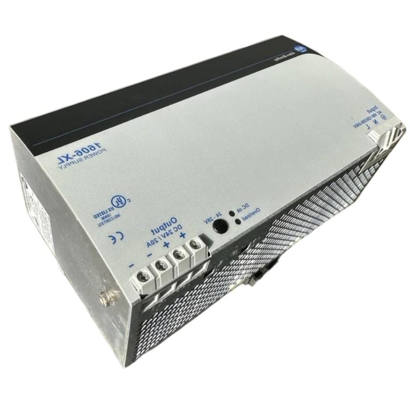
Allen Bradley 1606-XL480EP Power Supply Overload Fault Investigation
One common failure pattern is overload protection activation.
The diagnostic process:
Disconnect external loads.
Restart the power supply.
Reconnect circuits individually.
Identify the abnormal branch.
In one repair case, the 1606-XL480EP was connected to:
PLC Controller
Valve solenoids
Multiple proximity sensors
Interface relays
The system worked during testing but failed after production started. Current measurement showed the actual load reached 19.5 A during actuator operation, higher than the original design calculation.
After adding a separate supply branch for solenoid valves, the PLC system recovered without replacing the power supply.
Allen Bradley 1606-XL480EP Short Circuit Fault Diagnosis
Short circuits can trigger protective shutdown and appear as complete power supply failure.
Typical investigation steps:
Remove DC loads
Check resistance between positive and negative terminals
Inspect field wiring
Test devices individually
A common field pattern is damaged sensor cable insulation inside moving machine sections. The power supply repeatedly entered protection mode because the short circuit occurred only when the machine moved.
After replacing the damaged cable section, output voltage returned to 24.1 VDC and the control system operated normally.
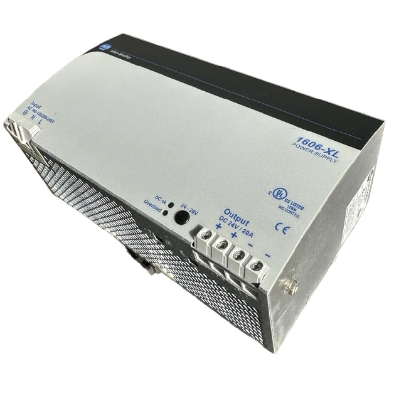
Allen Bradley 1606-XL480EP Repair Decision Based on Signal Analysis
Before repairing or replacing the unit, engineers should evaluate:
Input stability
Output ripple behavior
Load current
Temperature conditions
A power supply showing stable voltage under rated load is usually not the root cause of PLC faults.
During a troubleshooting case, engineers monitored the 1606-XL480EP output for 30 minutes:
Average output voltage: 24.05 VDC
Voltage fluctuation: less than 0.2 VDC
Load current: stable
The fault was eventually traced to a failing I/O module causing excessive current demand.
Allen Bradley 1606-XL480EP Fault Recovery and Preventive Maintenance
After fault correction, preventive actions should include:
Recording operating voltage values
Checking terminal tightness
Reviewing load distribution
Inspecting cabinet temperature
Updating system configuration documents
A maintenance team that records power supply performance data can identify degradation before unexpected shutdowns occur.
For industrial automation systems, the 1606-XL480EP troubleshooting process should always follow electrical evidence rather than assumption. Proper fault diagnosis protects PLC Controller availability and reduces unnecessary component replacement.

