Allen-Bradley 1606-XLB120E Power Supply Installation Guide
Time:2026-08-03 Browse: 9
Allen-Bradley 1606-XLB120E Power Supply Installation Overview
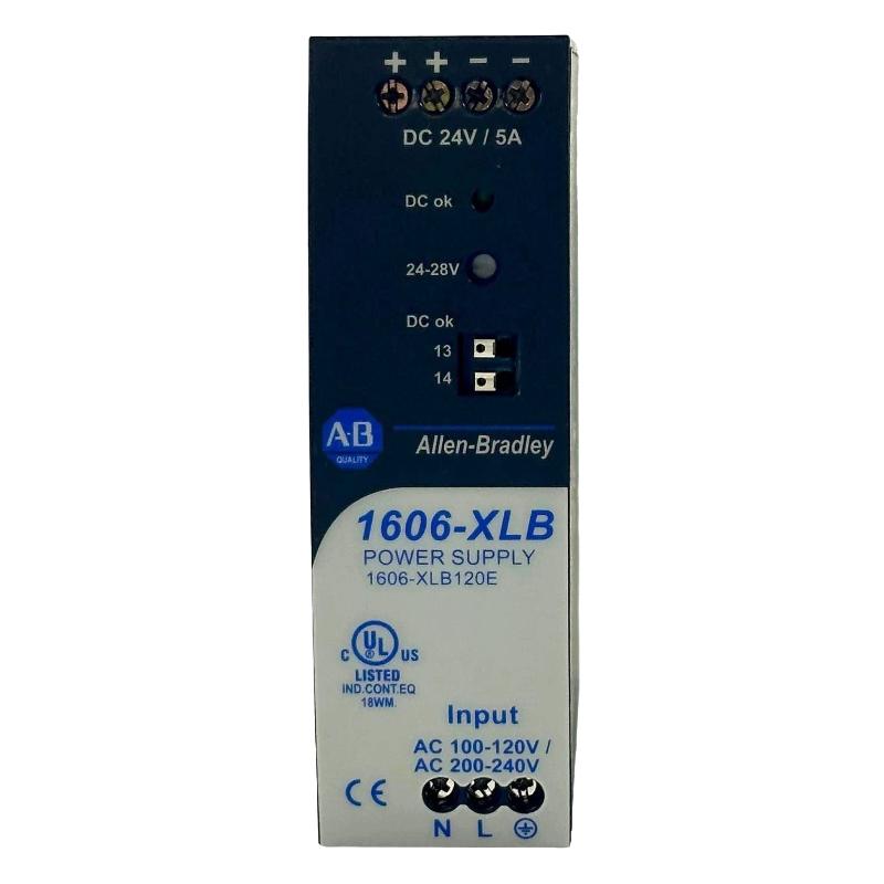
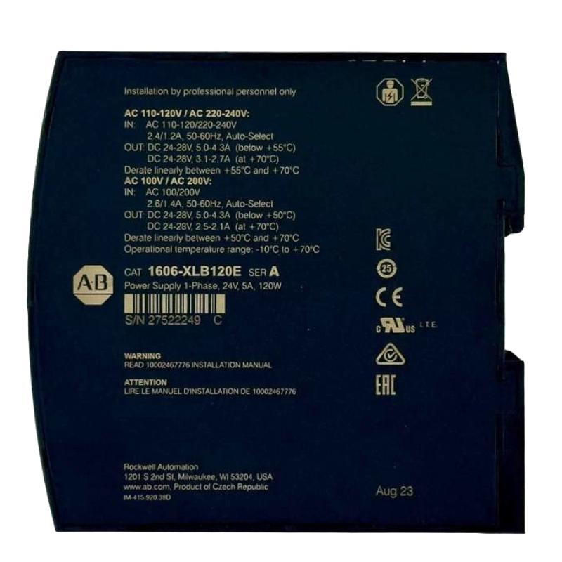
Allen-Bradley 1606-XLB120E installation issues are often caused by incorrect wiring, insufficient power calculation, or poor cabinet conditions rather than a damaged power supply. The 1606-XLB120E is a 24VDC industrial Power Supply designed for PLC Controller systems, automation panels, sensors, and control equipment requiring stable DC power. It provides a 120 W output capability with adjustable 24–28 VDC output for industrial applications.
In PLC systems, the power supply is the foundation of the entire System Configuration. A stable DC source ensures reliable operation of CPU modules, I/O modules, communication devices, and field sensors. During commissioning, engineers normally verify the power quality before investigating PLC or Module-related problems.
Allen-Bradley 1606-XLB120E Power Supply Installation Preparation
Before mounting the Allen-Bradley 1606-XLB120E Power Supply, the first engineering task is confirming the electrical demand of the complete control system.
The preparation process usually includes:
Checking PLC Controller current consumption
Calculating connected Module power requirements
Reviewing sensor and actuator loads
Confirming cabinet ventilation conditions
Inspecting grounding and protection circuits
A common mistake in field installations is selecting a power supply only based on PLC consumption while ignoring additional loads such as Ethernet switches, safety relays, solenoid valves, and transmitters.
For example, a PLC rack may require only 1.5 A, but after adding field devices the actual demand can exceed 4 A. This creates voltage instability during machine operation.
1606-XLB120E Power Supply Wiring and Electrical Setup
Correct wiring is essential for reliable operation. The AC input wiring, protective earth, and 24VDC output wiring should be properly separated inside the control cabinet.
During the Setup process, technicians normally check:
Input voltage connection
Earth grounding quality
DC polarity
Terminal tightening torque
Cable sizing
For PLC Controller applications, the 24VDC output should be measured before connecting the automation equipment. A normal unloaded measurement confirms that the Power Supply is operating correctly.
After connecting the PLC Module and field devices, engineers should measure the voltage at the farthest load point. A significant difference between the power supply output terminal and the PLC input terminal usually indicates cable resistance or poor terminal contact.
Allen-Bradley 1606-XLB120E Setup and Commissioning Validation
The Commissioning stage is not completed simply because the power indicator is active. Field engineers verify actual performance under operating conditions.
Typical validation includes:
Output voltage measurement
Load current inspection
PLC startup testing
Communication stability checking
Machine cycle observation
In one commissioning case, an automation cabinet experienced intermittent PLC Controller resets after installation. The initial assumption was a processor fault. During Fault Diagnosis, engineers measured the 24VDC line during motor startup and found the voltage dropped from 24.3 VDC to 21.9 VDC.
Further inspection showed that the 1606-XLB120E was supplying both control devices and high-current solenoid valves from the same circuit. After separating the loads and improving DC distribution, the voltage remained above 23.8 VDC during machine operation and the PLC system became stable.
Allen-Bradley 1606-XLB120E Installation Guide Long-Tail Keywords
Common engineering searches related to this Power Supply include:
Allen-Bradley 1606-XLB120E Power Supply Installation Guide
1606-XLB120E wiring and commissioning method
Allen-Bradley 24VDC PLC power supply setup
1606-XLB120E PLC Controller power configuration
A proper installation process reduces unnecessary PLC faults and improves long-term automation system reliability.

