Allen Bradley 1606-XLB120E Power Supply Installation Guide
Time:2026-08-04 Browse: 8
Allen Bradley 1606-XLB120E Power Supply Installation Overview
The Allen Bradley 1606-XLB120E power supply installation process requires correct AC input wiring, load verification, and DC output adjustment before the unit is placed into industrial service. In field applications, most commissioning issues are related to incorrect input voltage selection, poor terminal connections, or insufficient power capacity rather than internal power supply failure.
The 1606-XLB120E is a DIN rail mounted industrial power supply designed to provide stable DC power for PLC systems, remote I/O modules, sensors, and control devices. This Installation Guide focuses on practical setup methods used by engineers during panel assembly and machine commissioning.
Allen Bradley 1606-XLB120E System Preparation Before Setup
Before installing the Allen Bradley 1606-XLB120E power supply, the control cabinet environment should be evaluated. Engineers normally check the following conditions:
Available AC supply voltage and frequency
Total DC load consumption
Required current margin for startup conditions
Cabinet ventilation and mounting position
Grounding arrangement
A common engineering practice is to maintain approximately 20% to 30% power margin above the calculated continuous load. This prevents voltage drops when PLC Controllers, communication modules, or field sensors start simultaneously.
In one machine commissioning case, the original power calculation showed a 110W continuous load on a 120W power supply. During motor startup, the DC voltage dropped below the PLC operating threshold because the startup current was higher than expected. After replacing the calculation method with peak-load analysis, the system was redesigned with sufficient power reserve and the instability disappeared.
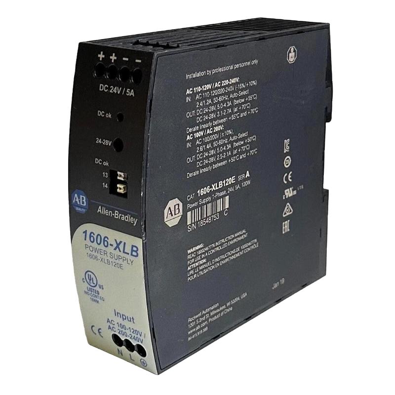
Allen Bradley 1606-XLB120E Power Supply Wiring Configuration
Correct wiring is the foundation of reliable operation. The AC input terminals should be connected according to the required supply voltage, while the DC output terminals must be connected with proper polarity.
During installation, engineers usually verify:
AC Line and Neutral connections
Protective earth connection
Positive and negative DC output polarity
Terminal tightening torque
Cable size suitability
A typical commissioning check includes measuring the DC output before connecting the PLC system.
Example field measurement:
No-load output voltage: 24.3 VDC
Normal PLC load voltage: 24.1 VDC
Voltage fluctuation: less than 0.2 VDC
Stable voltage readings indicate that the Allen Bradley 1606-XLB120E power supply is correctly integrated into the control system.
Allen Bradley 1606-XLB120E PLC System Commissioning Process
After wiring completion, the Setup and Commissioning procedure should follow an engineering validation sequence.
The commissioning workflow normally includes:
Apply AC input power
Confirm power supply indicator status
Measure DC output voltage
Connect PLC Controller and Module loads
Monitor voltage stability during operation
Verify communication and I/O response
In a real commissioning case, a PLC rack powered by the 1606-XLB120E showed intermittent communication loss. Diagnostic testing found the output voltage was stable, but the negative DC terminal had insufficient tightening force, causing momentary voltage interruption during cabinet vibration. After terminal correction, communication remained stable during extended machine operation.
Allen Bradley 1606-XLB120E Power Supply Installation Best Practices
For long-term reliability, industrial engineers typically apply several practical rules:
Separate high-current cables from signal wiring
Keep ventilation openings unobstructed
Avoid exceeding rated output current
Check terminal connections after machine vibration testing
Record initial voltage measurements during commissioning
The Allen Bradley 1606-XLB120E should be treated as part of the complete control power system rather than an isolated component. Proper System Configuration and installation practices directly influence PLC Controller stability and field device performance.

