Allen Bradley 1606-XLDNET8 DC Power Supply Installation Guide
Time:2026-08-12 Browse: 9
Allen Bradley 1606-XLDNET8 DC power supply installation should focus on correct AC input wiring, protected DC distribution, grounding, and controlled commissioning. The 1606-XLDNET8 belongs to the Allen Bradley Bulletin 1606-XLD family and is intended for industrial control systems where a stable DC supply is required for PLC controllers, I/O modules, communication equipment, sensors, and other automation loads.
In field installations, many power supply problems blamed on the PLC Controller are actually caused by loose terminals, undersized conductors, excessive voltage drop, or an incorrectly configured protective circuit. A proper Installation Guide therefore starts with the complete power path rather than the power supply alone.
Allen Bradley 1606-XLDNET8 DC Power Supply Role in an Automation System
The 1606-XLDNET8 is a DIN-rail industrial DC power supply designed to convert the available AC supply into regulated DC power for control equipment.
A typical control panel arrangement may look like:
AC Distribution → Circuit Protection → 1606-XLDNET8 → DC Distribution → PLC Controller / I/O Module / Sensor
This arrangement makes troubleshooting easier because the DC supply can be tested independently before downstream devices are energized.
During System Configuration, engineers should also consider the combined current demand of the connected equipment. A PLC rack, Ethernet switch, remote I/O station, sensors, relays, and interface modules may create a considerably higher real load than the nominal current shown on individual device labels.
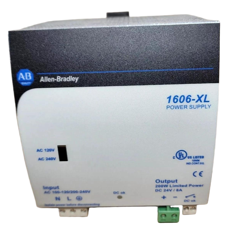
Allen Bradley 1606-XLDNET8 Installation Preparation
Before wiring the 1606-XLDNET8, verify the actual nameplate information against the electrical design.
Check:
Input voltage and frequency
Required DC output voltage
Total connected DC load
Control-panel short-circuit protection
Wire cross-section and terminal compatibility
DIN-rail mounting position
Ambient temperature
Required ventilation clearance
Protective earth arrangement
Do not select the upstream circuit breaker only from the power supply's output rating. The breaker must also be suitable for the actual AC input characteristics and the installation's fault-current conditions.
For a new control cabinet, it is useful to leave test points on the DC distribution side. This allows technicians to measure the supply before disconnecting PLC or Module wiring.
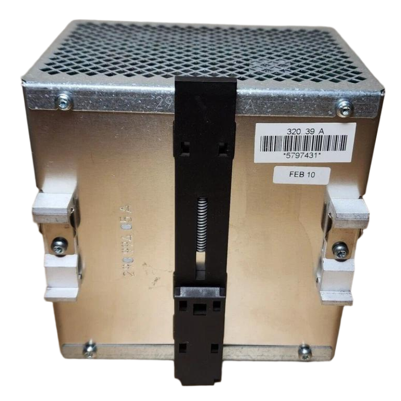
Allen Bradley 1606-XLDNET8 DIN Rail Mounting and Panel Layout
The power supply should be mounted securely on a suitable DIN rail and positioned where heat can dissipate naturally.
Avoid placing high-heat equipment immediately beside the 1606-XLDNET8. Variable frequency drives, braking components, large contactors, and other heat-producing devices can raise cabinet temperature and reduce the available power-supply margin.
A useful field rule is to inspect the complete thermal environment rather than looking only at the power supply's local temperature.
If the cabinet is densely packed, check:
Airflow path
Nearby heat sources
Enclosure temperature
Cable congestion
Accessibility of input and output terminals
A technically correct wiring design can still fail in service if the thermal design is poor.
Allen Bradley 1606-XLDNET8 Setup and System Configuration
After mechanical installation, configure the surrounding DC system according to the connected load.
For example, if the DC bus supplies:
One PLC Controller
Several digital I/O Modules
An Ethernet communication module
Multiple proximity Sensors
Interposing relays
the commissioning engineer should calculate both normal operating current and startup/inrush conditions.
The target is not simply to make the system power up. The objective is to maintain sufficient voltage at the most distant DC load during normal operation and switching events.
Measure the voltage at both:
Power Supply Output → Remote Load
If the voltage at the power supply is stable but the remote load voltage drops significantly, the investigation should move toward wiring resistance, terminal quality, distribution design, or load behavior rather than immediately replacing the power supply.
Allen Bradley 1606-XLDNET8 Commissioning Checks
Commissioning should be performed progressively.
First verify that the AC input is correct and that the protective earth arrangement is complete. Then energize the power supply without unnecessary downstream loads where the system design permits.
Measure:
AC input voltage
DC output voltage
DC voltage under normal load
Voltage at the remote PLC or Module
Voltage during major load switching
A stable DC reading with the system unloaded is not sufficient evidence of a healthy installation.
In one typical commissioning situation, a control panel showed a normal DC voltage at the power supply terminals but intermittent PLC communication resets occurred when several solenoid valves were energized. The power supply itself was initially suspected. The engineering check instead found a voltage drop across a poorly terminated DC distribution connection. After correcting the terminal and retesting under load, the PLC remained stable.
This is why commissioning should include measurements under realistic operating conditions.
Allen Bradley 1606-XLDNET8 Installation Validation
A completed Installation Guide should end with documented measurements rather than simply confirming that the green indicator is illuminated.
Record:
Input voltage
Output voltage
Loaded output voltage
Remote-load voltage
Cabinet temperature
DC load current where measurable
Protective device identification
PLC Controller startup condition
Communication status
Keep these values as the commissioning baseline.
That baseline becomes extremely useful later during Troubleshooting. If the DC output falls from a previously recorded value, engineers have an objective reference instead of relying on visual inspection.
Allen Bradley 1606-XLDNET8 Installation Troubleshooting Tips
If the 1606-XLDNET8 does not produce the expected DC output, work from the source toward the load.
Check the AC input first. Then inspect the protective device, input terminals, output terminals, DC distribution, and downstream loads.
A common mistake is to disconnect the PLC Controller immediately and replace the power supply. A better Fault Diagnosis approach is to determine whether the fault exists at the power-supply terminals or only after the DC power enters the field distribution network.
For long DC cable runs, measure directly at the remote Module or Sensor. A correct voltage at the supply does not prove that the remote equipment receives the same voltage.
Long-Tail Keywords for Allen Bradley 1606-XLDNET8 Installation
This Installation Guide naturally covers several useful search terms, including:
Allen Bradley 1606-XLDNET8 DC power supply installation
1606-XLDNET8 wiring guide
Allen Bradley 1606-XLDNET8 Setup
1606-XLDNET8 commissioning procedure
1606-XLDNET8 PLC power supply installation
Allen Bradley 1606-XLDNET8 DC output troubleshooting
1606-XLDNET8 industrial power supply wiring
Allen Bradley 1606-XLDNET8 System Configuration
1606-XLDNET8 PLC Controller power supply
1606-XLDNET8 Module power installation
These terms should be supported by actual technical information rather than repeated mechanically. In industrial SEO content, practical engineering detail provides more value than keyword density.

