Allen Bradley 1606-XLDNET8 DC Power Supply Troubleshooting Guide
Time:2026-08-12 Browse: 9
Allen Bradley 1606-XLDNET8 troubleshooting should begin by separating a genuine power-supply fault from a downstream overload, wiring problem, or unstable DC load. When a PLC Controller unexpectedly resets or an I/O Module disappears from the network, replacing the 1606-XLDNET8 immediately is often the wrong first move.
The most useful Fault Diagnosis method is to compare voltage at the power supply, distribution point, and affected load while the system is operating.
Allen Bradley 1606-XLDNET8 Fault Symptoms in the Field
A failing or incorrectly loaded 1606-XLDNET8 installation can produce several different symptoms:
PLC Controller resets
I/O Module communication loss
Ethernet equipment restarting
Sensors dropping offline
DC control relays chattering
Power supply protection behavior
Intermittent machine shutdowns
DC voltage falling when actuators operate
These symptoms do not automatically prove that the power supply has failed.
For example, if only one remote Sensor disappears while the PLC and other I/O remain operational, a complete power-supply failure is unlikely. The diagnostic path should move toward that sensor's branch circuit, connector, cable, and local voltage.
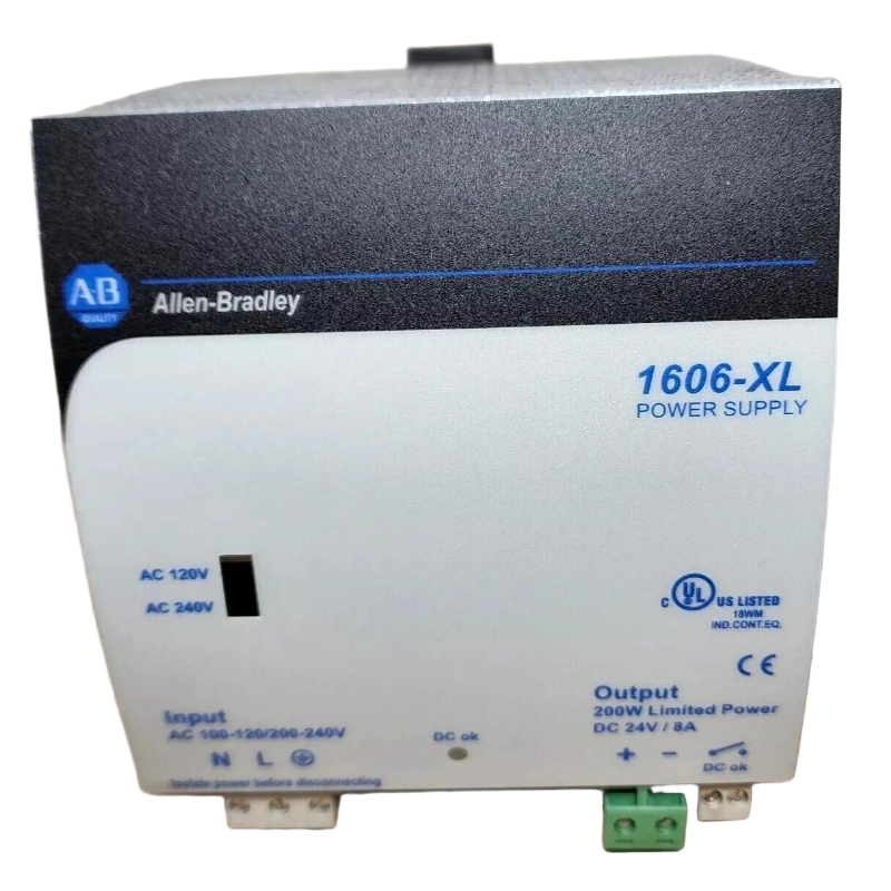
Allen Bradley 1606-XLDNET8 Troubleshooting Case: PLC Reset During Load Switching
In one representative field case, a PLC Controller operated normally for several minutes after startup but restarted whenever a group of DC loads was energized.
The first assumption was that the PLC firmware or controller hardware was unstable.
The engineering team instead monitored the DC bus during the switching event.
The result was revealing: the voltage at the power supply terminals remained comparatively stable, while the voltage measured at the PLC distribution point dropped sharply for a short period.
The diagnostic conclusion was therefore not “replace the PLC” and not immediately “replace the 1606-XLDNET8.”
The investigation moved to the DC distribution path. A high-resistance connection was found at a distribution terminal. Under normal load, the connection appeared acceptable. During the load transition, its voltage drop became significant enough to disturb the control system.
After the connection was corrected, the PLC reset condition disappeared.
This is a good example of why Troubleshooting should compare measurements rather than symptoms alone.
Allen Bradley 1606-XLDNET8 Overload and Short-Circuit Investigation
If the 1606-XLDNET8 enters a protection state or its output becomes unstable after additional equipment is connected, calculate the actual DC load.
Separate the loads into groups:
PLC Controller
I/O Modules
Communication Equipment
Sensors
Relays and Solenoids
Other DC Loads
Then identify which group was added or changed immediately before the fault appeared.
A useful diagnostic test is to remove nonessential branches one at a time while monitoring the DC output. If the output returns to normal after one branch is disconnected, that branch becomes the primary suspect.
The next question is whether the branch contains:
A shorted field device
Damaged cable insulation
Incorrect polarity
Excessive inrush current
A failed relay or solenoid
An unexpectedly high continuous load
This is more reliable than repeatedly cycling power and waiting for the fault to reappear.
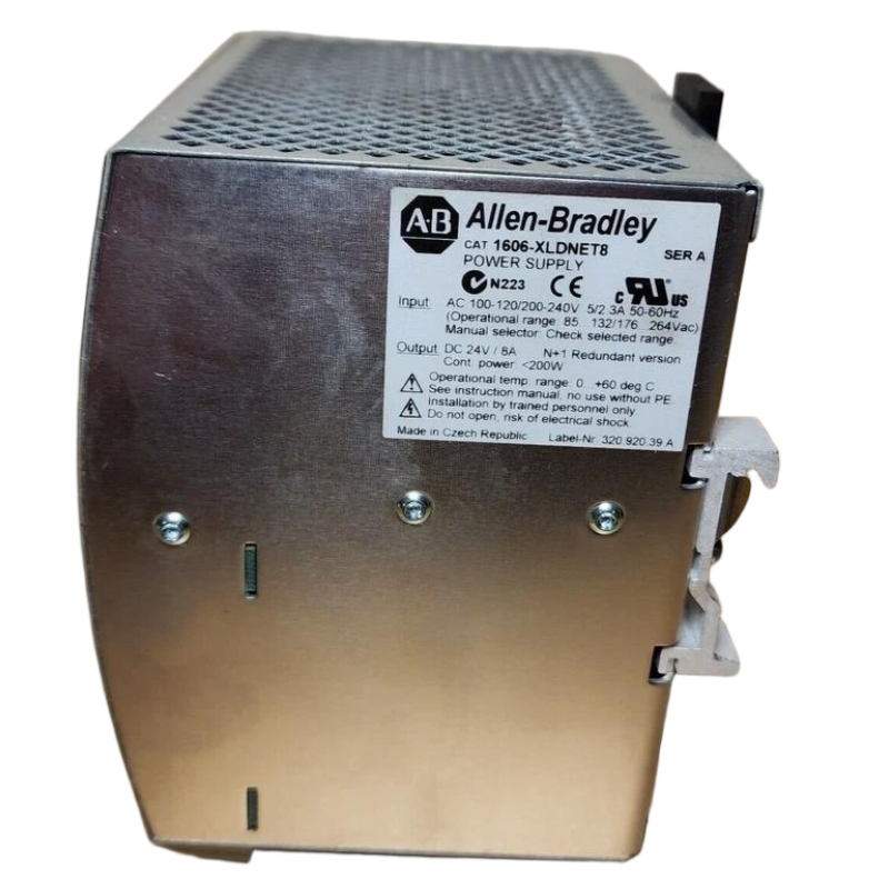
Allen Bradley 1606-XLDNET8 Intermittent Fault Investigation
Intermittent faults are more difficult because the power supply may test correctly when the machine is stopped.
Look for a relationship between the fault and a physical event:
Motor starts
Solenoid energizes
Valve changes state
Heater switches
Ethernet equipment starts
Remote I/O becomes active
Cabinet temperature rises
If the fault occurs only during one machine sequence, record the exact sequence and measure the DC bus during that event.
A useful Fault Diagnosis principle is:
“When does the voltage change?”
rather than simply:
“What is the voltage?”
A steady reading taken five minutes after the failure may hide the transient that actually caused the shutdown.
Allen Bradley 1606-XLDNET8 Communication Fault Troubleshooting
A PLC communication fault can sometimes originate from unstable DC power.
Suppose a remote communication Module repeatedly disappears and reconnects while the PLC diagnostic log reports communication timeouts.
Before replacing the network hardware, check:
Module supply voltage
Voltage during communication activity
Module restart behavior
DC branch terminals
Shared power loads
Grounding and wiring condition
If the communication Module loses power for a fraction of a second, the network symptom can look exactly like a communication cable problem.
This is particularly important in distributed control panels where a single DC supply feeds both control electronics and field loads.
Allen Bradley 1606-XLDNET8 Sensor Power Fault Diagnosis
Sensors can create misleading symptoms.
For example, a proximity Sensor may operate correctly during machine idle conditions but fail when several outputs switch simultaneously.
Measure the Sensor supply directly at the Sensor connector if possible.
Compare:
Supply voltage at 1606-XLDNET8
with
Supply voltage at Sensor
and then compare both measurements during the fault.
If the supply remains stable at the power supply but drops at the Sensor, the likely causes include cable resistance, damaged conductors, poor terminal contact, or excessive branch loading.
If the voltage collapses at the power supply itself, the investigation should return to the total DC load and power-supply operating condition.
Allen Bradley 1606-XLDNET8 Repair Decision: Supply or External Circuit?
A practical repair decision can be made using three observations.
Case A — Abnormal output directly at the power supply
Investigate input conditions, overload, short circuit, protection behavior, and the power supply itself.
Case B — Normal power-supply output but low remote voltage
Investigate cable resistance, terminals, connectors, branch protection, and distribution architecture.
Case C — Normal voltage everywhere but one device fails
Investigate the individual PLC Controller, Module, Sensor, communication device, or its configuration.
This prevents unnecessary component replacement.
Allen Bradley 1606-XLDNET8 System Configuration Checks After Repair
After correcting a power fault, do not stop when the PLC Controller starts.
Verify the complete System Configuration:
PLC startup
I/O status
Communication modules
Sensor operation
Output switching
Alarm history
DC voltage under load
Machine sequence
Run the equipment through the operating condition that originally produced the failure.
A repair is not validated simply because the alarm disappears after a cold restart.
Allen Bradley 1606-XLDNET8 Troubleshooting and Maintenance Measurements
For recurring industrial problems, record a small set of baseline values during healthy operation.
Useful records include:
| Measurement | Normal Condition |
|---|---|
| AC input | Recorded commissioning value |
| DC output | Recorded commissioning value |
| Remote PLC voltage | Recorded loaded value |
| Remote Module voltage | Recorded loaded value |
| DC load current | Recorded operating value |
| Cabinet temperature | Recorded operating value |
When a future fault occurs, compare the new measurements against this baseline.
That turns Troubleshooting from guesswork into trend analysis.
Allen Bradley 1606-XLDNET8 Fault Diagnosis: Practical Engineering Logic
The most important lesson from 1606-XLDNET8 Troubleshooting is to follow the electrical path.
Do not assume:
PLC reset = PLC failure
Do not assume:
Communication loss = Ethernet fault
Do not assume:
Low Sensor signal = Sensor failure
Instead, establish where the electrical condition changes.
For a DC power system, the diagnostic path should generally be:
Input → Power Supply → Distribution → Load → Signal
Once the abnormal point is identified, repair becomes much more targeted.
Long-Tail Keywords for Allen Bradley 1606-XLDNET8 Troubleshooting
Relevant long-tail search terms include:
Allen Bradley 1606-XLDNET8 troubleshooting
1606-XLDNET8 DC output fault
Allen Bradley 1606-XLDNET8 Fault Diagnosis
1606-XLDNET8 PLC power supply troubleshooting
Allen Bradley 1606-XLDNET8 PLC Controller reset
1606-XLDNET8 output voltage problem
Allen Bradley 1606-XLDNET8 overload troubleshooting
1606-XLDNET8 communication fault
Allen Bradley 1606-XLDNET8 Module power fault
1606-XLDNET8 Sensor power troubleshooting
Allen Bradley 1606-XLDNET8 repair diagnosis
The strongest troubleshooting content is not the longest list of possible faults. It is the ability to connect a symptom with a measurement, identify the point where the electrical condition changes, and then verify the repair under the same operating conditions that produced the original failure.

