Allen Bradley 1606-XLE120EE Power Supply Installation Guide
Time:2026-08-14 Browse: 13
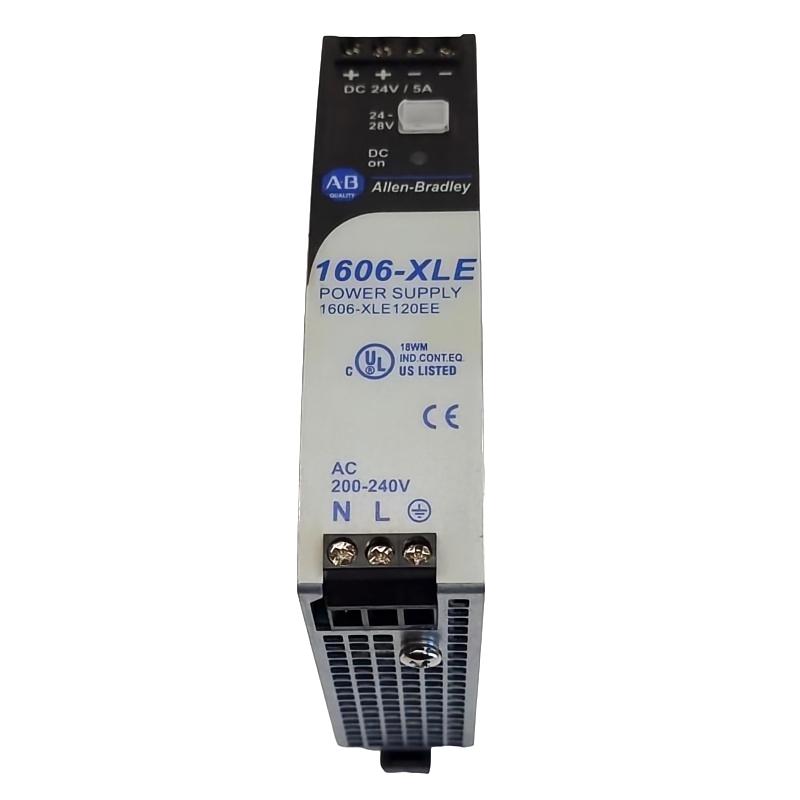
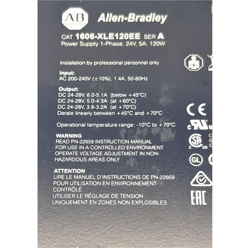
Allen Bradley 1606-XLE120EE installation should be treated as a 240V AC to 24V DC power conversion task, with particular attention to protective earth, input voltage selection, DIN-rail mounting, ventilation, and the actual DC load. The 1606-XLE120EE is a 120 W single-phase Power Supply XLE unit rated for 180–264V AC input and 24–28V DC output at up to 5 A.
For PLC panels, the important point is not simply getting 24 VDC at the terminals. A good Setup / Commissioning process confirms that the power supply remains stable when PLC controllers, I/O modules, sensors, relays, and communication equipment are connected simultaneously.
Allen Bradley 1606-XLE120EE Power Supply Application
The 1606-XLE120EE belongs to the Allen-Bradley 1606-XLE Essential power supply family. It is designed for single-phase industrial control panels where a compact 24 VDC source is required.
Its main electrical characteristics are:
Input: 180–264V AC
Nominal input: 200V AC at 50/60 Hz
Output: 24–28V DC
Rated output current: 5 A
Rated output power: 120 W
Typical efficiency: 90.2%
Ripple and noise: up to 50 mV
Hold-up time: more than 80 ms at 120V AC
DIN-rail mounting
IP20 protection
Screw terminal connections
Width: 32 mm
Height: 124 mm
Depth: 117 mm
Weight: approximately 0.5 kg according to the current Rockwell product data.
The manufacturer identifies the product as having multiple possible countries of origin, depending on manufacturing location.
1606-XLE120EE Installation Preparation
Before mounting the Power Supply, check the panel power architecture rather than connecting the unit immediately.
A typical control cabinet may contain:
AC incoming supply → circuit protection → 1606-XLE120EE → 24VDC distribution → PLC Controller / I/O / sensors / relays
Calculate the expected DC load first.
For example, if the control system contains:
PLC Controller: 0.8 A
Remote I/O modules: 0.7 A
Sensors: 0.6 A
Ethernet equipment: 0.8 A
Relays and solenoids: 0.9 A
the estimated continuous load is approximately 3.8 A.
That is below the 5 A rating of the 1606-XLE120EE, but the engineer should still consider startup current and future expansion. The unit provides a 20% power reserve under its specified operating conditions, which can be useful for moderate load transients.
Allen Bradley 1606-XLE120EE DIN Rail Mounting
The power supply is designed for 35 mm DIN-rail mounting. The manufacturer's installation material specifies the use of suitable 35 mm DIN rails and recommends maintaining clearance around the device for heat dissipation.
In a practical panel installation, avoid placing the 1606-XLE120EE directly against a high-temperature device such as a large variable frequency drive.
The published installation guidance recommends approximately:
40 mm clearance above
20 mm clearance below
5 mm clearance on each side
when operating continuously at full load. Additional clearance is advisable if the neighboring equipment is a heat source.
The output terminals should normally be positioned toward the top and the input terminals toward the bottom. The power supply uses convection cooling, so cable ducts or other objects should not unnecessarily obstruct the ventilation openings.
1606-XLE120EE Wiring and Protective Earth
The most important wiring point is the protective earth connection.
Do not use a mounting screw on the enclosure as a substitute for the designated PE terminal. Rockwell's installation instructions specifically require a proper protective-earth connection.
The AC input should be wired according to the terminal identification on the actual unit and the applicable electrical code.
For the DC side, connect the 24 VDC output to the control-system distribution terminals. Keep PLC and sensor power wiring organized separately from high-current switching conductors where practical.
This matters because a technically correct 24 VDC voltage can still produce unstable PLC operation if wiring is poorly routed or if inductive loads introduce excessive disturbances.
Allen Bradley 1606-XLE120EE Output Voltage Setup
The nominal output is 24 VDC, with an adjustment range of 24–28 VDC. The product is factory stabilized and provides up to 5 A at the nominal 24 V output.
For a conventional PLC Controller installation, there is usually no reason to increase the output unnecessarily.
A sensible commissioning target is to verify approximately 24 VDC at the power supply and then check the voltage again at the PLC terminals under operating load.
For example:
Power supply terminals: 24.1 VDC
PLC input terminals: 23.9 VDC
A small distribution drop is normally far more useful diagnostically than simply checking the voltage with no load.
1606-XLE120EE Setup and Commissioning Checks
The commissioning process should be performed progressively.
First energize the AC input with the DC load isolated. Confirm that the unit starts normally and that the output voltage is within the expected range.
Next connect the PLC Controller and basic I/O load.
Then add field devices and other 24 VDC consumers in groups.
This approach makes Fault Diagnosis considerably easier. If the voltage collapses only after a particular group is connected, the engineer has narrowed the fault area without replacing the power supply unnecessarily.
The Allen-Bradley data specifies an input inrush current of approximately 30 A on the current product page, so upstream protection and switching devices should be selected with the actual inrush characteristic in mind.
Real Commissioning Case: 24 VDC Drops After PLC Startup
In one typical commissioning situation, a 24 VDC control panel appeared normal with the PLC disconnected. The measured output was 24.2 VDC.
After the PLC Controller, Ethernet switch, and several sensors were energized, the measured voltage dropped to approximately 22.8 VDC.
The first assumption was that the 1606-XLE120EE was undersized.
However, the current measured at the power supply was below 5 A. The investigation therefore moved downstream.
The engineer measured the voltage at three locations:
Power supply: 24.2 VDC
Distribution terminal: 23.8 VDC
Remote I/O cabinet: 22.8 VDC
The problem was excessive voltage drop in a long, undersized DC cable rather than a defective power supply.
After the DC distribution wiring was corrected, the remote I/O voltage increased to approximately 23.9 VDC and the intermittent communication alarms disappeared.
This is a useful field lesson: a power supply fault should not be diagnosed only from the voltage measured directly across its output terminals.
Allen Bradley 1606-XLE120EE System Configuration Considerations
The 1606-XLE120EE is not a PLC Controller or communication module. It is the DC power source supporting those devices.
During System Configuration, document:
Total continuous DC load
Expected peak load
PLC Controller current
I/O current
Sensor current
Communication equipment current
Fuse or breaker rating
DC distribution cable size
Grounding arrangement
Cabinet ambient temperature
The manufacturer's data specifies a 120 W output and 5 A rated current, but actual application loading must account for temperature and installation conditions.
1606-XLE120EE Installation Fault Prevention
Several simple practices prevent a large percentage of field problems:
Do not install the unit in a location where airflow is blocked.
Do not connect it to an AC supply outside its specified operating range.
Do not ignore protective earth.
Do not assume that a 24 V reading without load proves the DC system is healthy.
Do not repeatedly reset a tripped protection device without determining why the trip occurred.
The manufacturer's installation guidance also warns against opening or modifying the power supply and states that internal fuse operation can indicate an internal defect rather than a field-serviceable condition.
Long-Tail Keywords for Allen Bradley 1606-XLE120EE Installation
Natural search phrases associated with this Installation Guide include:
Allen Bradley 1606-XLE120EE installation guide, 1606-XLE120EE wiring, 1606-XLE120EE setup, 1606-XLE120EE commissioning, 1606-XLE120EE 24V power supply installation, Allen Bradley 1606-XLE120EE DIN rail mounting, 1606-XLE120EE PLC power supply, 1606-XLE120EE system configuration, 1606-XLE120EE output voltage setup, and Allen Bradley 1606-XLE120EE power supply wiring.
Final Commissioning Judgment
A successful 1606-XLE120EE commissioning is not simply “24 V is present.”
The more useful acceptance test is:
Correct AC input → stable 24 VDC → acceptable voltage at the actual load → stable operation during startup → acceptable voltage under normal load → no excessive heating or nuisance protection trips.
That sequence gives the commissioning engineer a reliable baseline for later Troubleshooting and Fault Diagnosis.

