Allen Bradley 1606-XLE120EE Power Supply Troubleshooting Guide
Time:2026-08-14 Browse: 12
Allen Bradley 1606-XLE120EE low-output-voltage faults should not automatically be treated as power supply failure. The 1606-XLE120EE is a 120 W, 5 A single-phase power supply designed to provide 24–28V DC from a 180–264V AC input, so a proper Fault Diagnosis should distinguish between an AC input problem, excessive DC load, wiring loss, thermal derating, and an internal power-supply fault.
This distinction is particularly important in PLC systems because a marginal 24 VDC supply can create secondary symptoms such as PLC resets, sensor errors, I/O faults, and communication interruptions.
Allen Bradley 1606-XLE120EE Low Voltage Fault Symptoms
A typical low-voltage event may appear in several ways:
PLC Controller unexpectedly restarts
I/O modules report undervoltage conditions
Sensors intermittently switch off
Ethernet equipment loses communication
Relays chatter during machine startup
24 VDC measures normally with no load but falls under load
Faults appear only after the cabinet has been running for several hours
The last symptom is especially useful.
If the system operates correctly when cold and fails after heating up, the engineer should investigate thermal conditions and load margin before replacing the 1606-XLE120EE.
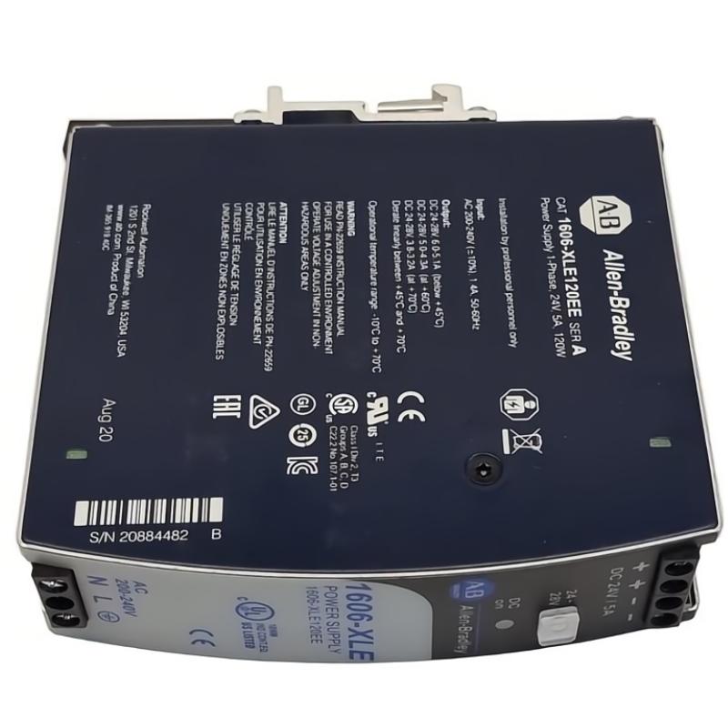
1606-XLE120EE Fault Diagnosis: Start With the Measurement
A useful Troubleshooting approach begins with three measurements rather than one.
Measure:
M1 — AC input at the power supply
M2 — DC output directly at the 1606-XLE120EE
M3 — DC voltage at the PLC or affected load
Suppose the readings are:
AC input: 231 VAC
Power supply output: 24.1 VDC
PLC terminal: 22.6 VDC
The power supply is maintaining the expected output. The significant voltage loss is between the supply and the PLC.
Replacing the 1606-XLE120EE in this situation would not correct the actual fault.
Allen Bradley 1606-XLE120EE Overload Troubleshooting
The rated output current is 5 A at 24 VDC, corresponding to 120 W. The unit also provides a specified power reserve under suitable operating conditions.
An overload can be deceptive.
A panel may have a normal continuous current of 4.2 A but experience a considerably higher transient current when multiple solenoids, contactors, or actuators operate simultaneously.
This can create a fault pattern such as:
Machine idle → normal 24 V
PLC running → normal 24 V
Several outputs energize → DC voltage falls
Outputs release → voltage recovers
That pattern points toward load behavior rather than an immediate conclusion of internal power-supply failure.
1606-XLE120EE Thermal Fault Diagnosis
Temperature is another important diagnostic variable.
The current Rockwell specification lists a derating characteristic of 3 W/°C, and the power supply is convection cooled.
A cabinet with poor airflow can therefore produce a fault that looks electrical at first.
Check:
Cabinet ambient temperature
Clearance around the power supply
Nearby heat-producing equipment
Blocked ventilation openings
Actual DC load
Temperature before and after the fault occurs
If the 24 VDC output is stable at 20°C but falls after the cabinet reaches a significantly higher operating temperature, thermal investigation becomes more important.
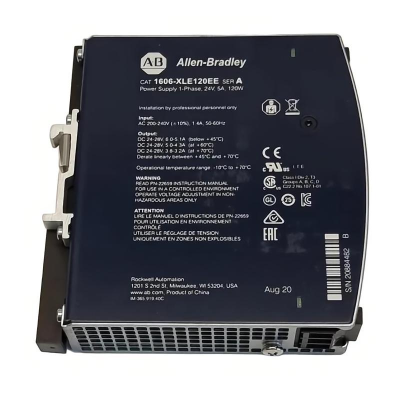
Real Field Case: PLC Resets After Several Hours
In one field troubleshooting case, a PLC Controller operated normally during the first part of the production shift.
After approximately two hours, the PLC began restarting intermittently.
The initial assumption was a PLC hardware problem because the controller itself showed no permanent diagnostic fault.
The engineer measured the 1606-XLE120EE output immediately after a restart and recorded 23.8 VDC.
That measurement appeared acceptable.
However, the voltage was measured again during simultaneous operation of several DC loads.
The result was:
Idle: 24.0 VDC
Normal production: 23.5 VDC
Peak actuator operation: 21.9 VDC
The next measurement was made at the PLC terminals. During the same event, the PLC supply dropped below the level required for reliable operation.
The investigation then found that several solenoid valves had been added during a machine modification without recalculating the 24 VDC load.
The power supply was operating close to its practical limit, and the additional switching load produced the intermittent voltage collapse.
The corrective action was not simply replacing the PLC. The DC load distribution was redesigned and the high-current field loads were separated from the sensitive control supply.
1606-XLE120EE Wiring Faults and Voltage Drop
A wiring fault can produce symptoms almost identical to a weak power supply.
Pay particular attention to:
Loose screw terminals
Undersized DC conductors
Long cable runs
Oxidized connections
Shared return conductors
Poor terminal-block connections
High-current loads sharing the same branch
For Fault Diagnosis, voltage-drop testing under load is more informative than resistance testing on a disconnected circuit.
For example:
1606-XLE120EE output: 24.1 VDC
PLC cabinet distribution: 24.0 VDC
Remote sensor panel: 21.7 VDC
The measurement clearly directs the investigation toward the distribution path.
Allen Bradley 1606-XLE120EE AC Input Faults
The 1606-XLE120EE is specifically designed for the 180–264V AC operating range.
If the input voltage is unstable, the DC output can also become unstable.
Measure the AC voltage while the system is actually operating rather than only with the machine stopped.
A loose upstream terminal can produce a normal voltage at idle and a voltage drop when other equipment starts.
A useful diagnostic sequence is:
AC input stable → DC output stable → DC load stable
If the first condition fails, troubleshooting the downstream PLC Controller is premature.
1606-XLE120EE Ripple and Noise Investigation
The specified maximum ripple and noise is 50 mV.
If the DC voltage appears correct on a multimeter but sensitive sensors or communication equipment continue to malfunction, waveform quality deserves attention.
An oscilloscope can reveal disturbances that a basic meter will not show.
This is particularly useful when the symptoms are:
Encoder count errors
Sensor false triggering
Intermittent communication loss
PLC input flicker
Analog signal instability
The objective is not simply to prove that the output is “24 V.” The objective is to determine whether the DC supply remains electrically clean during the actual machine cycle.
1606-XLE120EE Internal Fault Diagnosis
If the AC input is correct, the load is within the expected range, wiring losses are acceptable, ventilation is adequate, and the DC output remains abnormally low, an internal power-supply fault becomes more plausible.
The 1606-XLE120EE has stabilized output and internal protection features.
However, field technicians should not treat the enclosure as a serviceable electronic assembly.
Rockwell's installation documentation warns against opening or modifying the device and notes that internal fuse operation can indicate an internal defect.
For a suspected internal failure, the practical approach is to isolate the unit, verify the surrounding circuit, and follow the applicable replacement or service procedure rather than attempting component-level repair on the energized device.
Allen Bradley 1606-XLE120EE Troubleshooting Logic
A useful diagnostic decision tree is:
Low 24 VDC
→ Check AC input
→ If AC is low or unstable: inspect upstream supply and protection
→ If AC is correct: measure DC directly at the power supply
→ If DC is correct at the supply: check distribution voltage drop
→ If DC is low at the supply: measure load current
→ If load is excessive: isolate additional loads
→ If load is acceptable: investigate thermal conditions
→ If all external conditions are normal: evaluate the power supply itself
This method prevents a common maintenance mistake: replacing an expensive PLC Controller because the actual problem is a 24 VDC distribution fault.
1606-XLE120EE System Configuration and Recovery
After correcting the fault, do not stop at the first successful PLC restart.
Record:
AC input voltage
DC output voltage
DC load current
Voltage at the PLC
Voltage at remote I/O
Cabinet temperature
Peak-load behavior
Alarm history
A good repair should leave measurable evidence that the original fault has been removed.
For example, if the original PLC terminal voltage fell to 21.9 VDC during peak loading and the corrected system remains at 23.7–24.0 VDC during the same machine cycle, the recovery is much more convincing than simply observing that the PLC restarted successfully.
Long-Tail Keywords for Allen Bradley 1606-XLE120EE Troubleshooting
Relevant long-tail search terms include:
Allen Bradley 1606-XLE120EE troubleshooting, 1606-XLE120EE fault diagnosis, 1606-XLE120EE low voltage fault, 1606-XLE120EE 24V output problem, 1606-XLE120EE power supply failure, 1606-XLE120EE PLC power problem, Allen Bradley 1606-XLE120EE voltage drop, 1606-XLE120EE overload troubleshooting, 1606-XLE120EE thermal fault, 1606-XLE120EE output voltage diagnosis, and 1606-XLE120EE repair troubleshooting.
Final Fault Diagnosis for 1606-XLE120EE
The most reliable Troubleshooting principle for the Allen Bradley 1606-XLE120EE is simple: diagnose the complete 24 VDC power path, not just the power supply.
A stable reading at the supply terminals does not prove that the PLC Controller is receiving stable voltage. Conversely, a low reading at the PLC does not automatically mean the 1606-XLE120EE has failed.
Check the AC input, measure the DC output under real load, trace voltage through the distribution system, evaluate temperature and current, and only then make the replacement decision.
That approach is faster, produces better Fault Diagnosis records, and avoids unnecessary replacement of healthy automation hardware.

