Allen Bradley 1336-SN-SP15A Inverter Snubber PCB Installation Guide
Time:2026-08-16 Browse: 12
The Allen Bradley 1336-SN-SP15A is an inverter snubber PCB used with 1336STEF drives in high-power 575 V applications. Rockwell Automation identifies it as a Snubber PCB accessory and specifies three boards per drive.
Allen Bradley 1336-SN-SP15A Inverter Snubber Application
The 1336-SN-SP15A is not a standalone inverter or control Module. It is part of the power-stage protection system inside a 1336STEF drive.
Its function is associated with controlling transient electrical effects around the inverter switching circuit. For this reason, installation should be treated as a power-electronics service operation rather than a routine PCB replacement.
Rockwell Automation lists the part as a 575 V inverter snubber PCB for 1336STEF applications. The manufacturer's current product information specifies the 300–650 HP range, while the historical spare-parts documentation associates 1336-SN-SP15A with 300–800 HP A21–A23 configurations. The exact drive catalog number and frame should therefore be verified before installation.
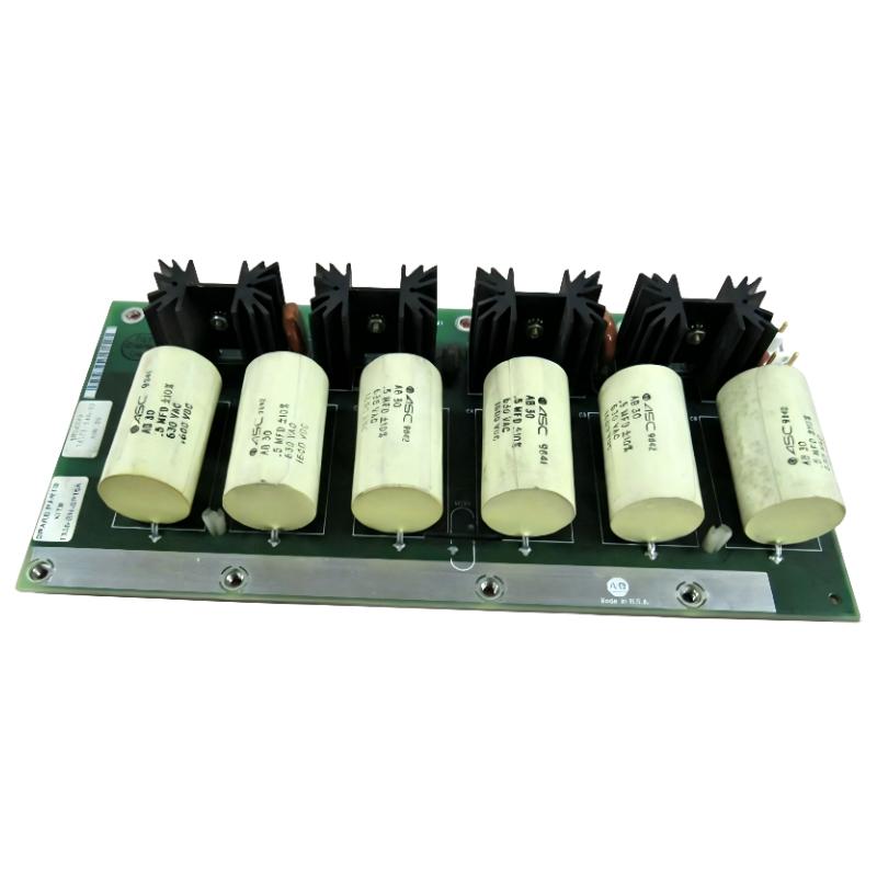
1336-SN-SP15A Installation Preparation
Before opening the drive, isolate the incoming power and follow the drive's discharge and lockout procedure. A large 1336 drive can retain hazardous DC-bus voltage after the input supply has been removed.
The preparation should include:
Correct 1336-SN-SP15A replacement boards
Drive catalog number and frame information
Electrical drawings or service documentation
Insulated electrical tools
Suitable voltage measurement equipment
ESD protection for PCB handling
Inspection lighting
Do not begin by removing the existing snubber board. First document its physical position, wiring, connector orientation, mounting hardware, and board identification.
The Rockwell parts information indicates that three 1336-SN-SP15A boards are required per drive, so replacing only one board in a three-board arrangement should not be treated as an equivalent complete kit replacement without a specific engineering reason.
Allen Bradley 1336-SN-SP15A Wiring and PCB Inspection
Before installation, compare the replacement PCB with the removed board.
Check:
Board identification
Connector positions
Terminal locations
Mounting points
PCB condition
Signs of overheating
Discoloration around power components
Damaged terminals or conductors
Do not force a connector into position simply because the mechanical location appears close.
In high-power drives, a loose connection can create localized heating and eventually damage the replacement snubber circuit. The condition of the surrounding bus and inverter hardware should therefore be checked at the same time.
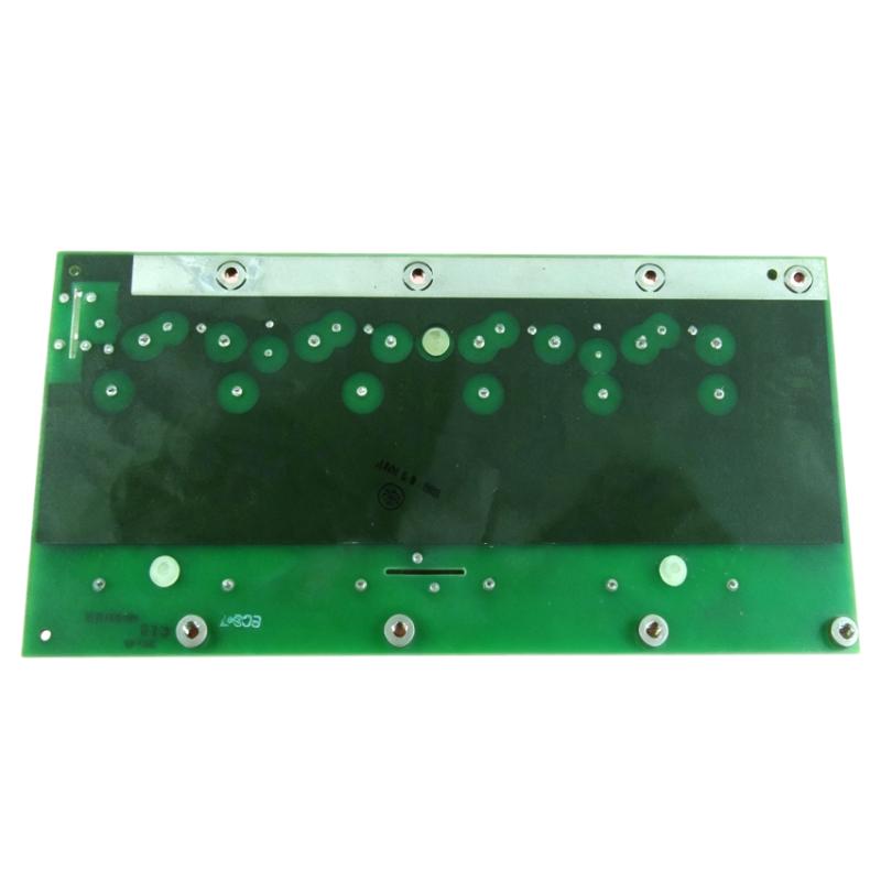
1336-SN-SP15A Setup and Installation Procedure
The installation sequence should follow the service documentation for the specific 1336STEF frame.
After the drive has been safely isolated and the DC bus has been confirmed discharged:
Record the original board positions.
Inspect the surrounding inverter power section.
Remove the failed snubber PCB without disturbing adjacent assemblies unnecessarily.
Compare the replacement board with the original.
Install the PCB in the correct mechanical position.
Reconnect each conductor or connector to its original location.
Check that no wire is trapped against the PCB or heatsink.
Repeat the inspection for the remaining snubber positions.
Verify that all three required positions are correctly populated where applicable.
The purpose of this process is not simply to make the drive electrically complete. It is to ensure that the replacement board is installed in the same electrical configuration as the original system.
Allen Bradley 1336-SN-SP15A Commissioning Checks
After installation, do not immediately apply full operating load.
A practical Commissioning approach is:
Visual inspection → resistance checks → controlled energization → drive diagnostics → unloaded operation → gradual load test
Check the DC-bus and input conditions according to the drive's service procedure. During the first power-up, observe for abnormal noise, smoke, smell, rapid heating, or immediate protective trips.
If a newly installed snubber PCB fails immediately, replacing it again without investigating the inverter power stage is poor Fault Diagnosis practice.
A damaged switching device, abnormal DC-bus condition, shorted component, or wiring problem may be the actual cause.
1336-SN-SP15A Installation Validation in the Field
In one high-power drive service case, a replacement snubber PCB was initially suspected to be defective because the drive produced an abnormal inverter fault shortly after startup. Instead of installing another PCB, the technician compared the three snubber positions and inspected the adjacent power circuitry.
The inspection found evidence of thermal stress around the inverter section. The troubleshooting process was expanded from the PCB itself to the complete inverter power stage.
This type of diagnostic thinking is important with the 1336-SN-SP15A: a snubber PCB can be the failed component without being the original cause of the failure.
Allen Bradley 1336-SN-SP15A Installation Guide Long-Tail Keywords
This Installation Guide covers common search terms such as:
Allen Bradley 1336-SN-SP15A installation
Allen Bradley 1336-SN-SP15A inverter snubber PCB
1336-SN-SP15A replacement procedure
1336-SN-SP15A 575 V installation
1336-SN-SP15A 1336STEF setup
Allen Bradley inverter snubber PCB commissioning
1336-SN-SP15A drive service procedure
1336-SN-SP15A System Configuration and inspection

