Allen Bradley 1336-SN-SP15A Inverter Snubber Fault Troubleshooting Guide
Time:2026-08-16 Browse: 11
Allen Bradley 1336-SN-SP15A faults should not be diagnosed by replacing the snubber PCB alone. Because this component operates in the inverter power section of a high-power 1336STEF drive, a failed snubber board can be the result of an underlying switching, bus, connection, or thermal problem. Rockwell Automation specifies the 1336-SN-SP15A as a 575 V Snubber PCB for 1336STEF drives.
Allen Bradley 1336-SN-SP15A Fault Symptoms
A defective inverter snubber circuit may be associated with several different symptoms:
Inverter-related drive faults
Abnormal power-stage behavior
Visible PCB damage
Burn marks or localized overheating
Repeated failure after PCB replacement
Unusual electrical noise
Drive trips during acceleration or high load
Failure occurring immediately after energization
The symptom alone is not sufficient for Fault Diagnosis.
For example, a burned snubber PCB does not automatically prove that the PCB itself was defective. A switching device or abnormal transient condition may have caused the damage.
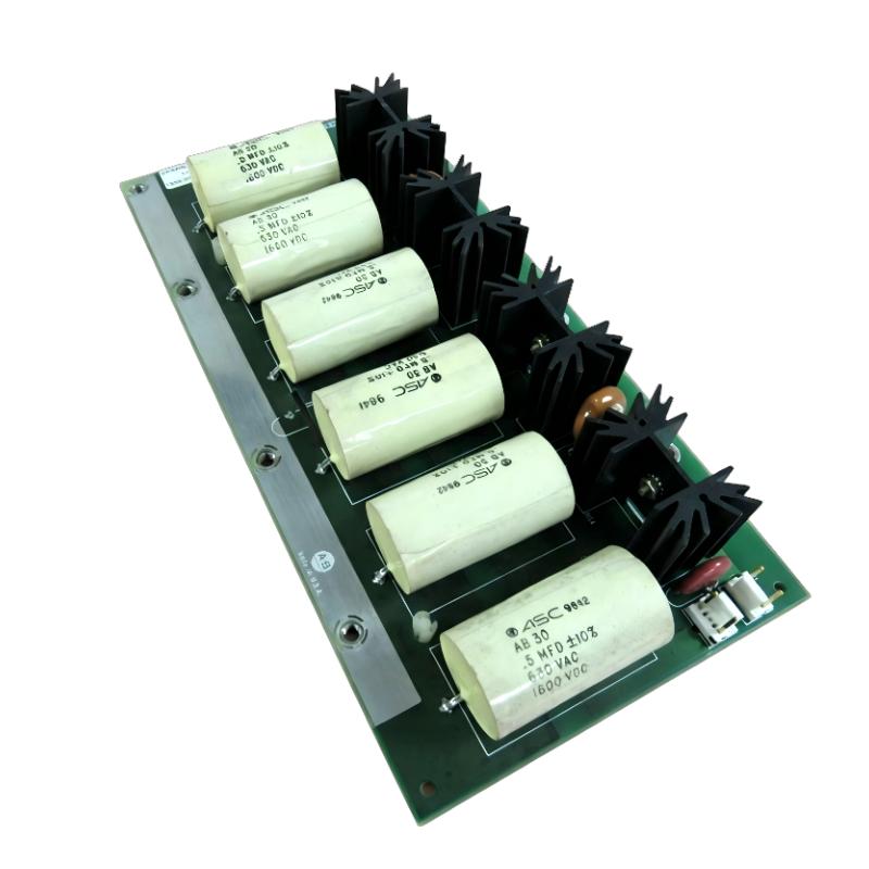
1336-SN-SP15A Troubleshooting Starts With the Failure Pattern
The first question should be when the fault occurs.
If the drive trips immediately after power is applied, investigate the inverter power section and DC-bus condition before focusing on operating-load behavior.
If the fault appears only during acceleration, examine the switching and load conditions.
If the same snubber position repeatedly fails while the other positions remain normal, compare that physical circuit with the unaffected positions.
This comparison is often more informative than simply reading the drive fault code.
Allen Bradley 1336-SN-SP15A Fault Diagnosis Logic
A practical diagnostic path is:
Drive fault → affected inverter section → snubber PCB → surrounding power circuit → operating condition
Inspect the PCB first for obvious physical evidence:
Cracked components
Burned areas
Discoloration
Loose connections
Damaged terminals
Carbonized PCB material
Evidence of overheating
Then inspect the surrounding inverter circuitry.
The key engineering question is:
Did the snubber PCB cause the fault, or did another power-stage fault damage the snubber PCB?
That distinction determines whether replacing the board will actually repair the drive.
1336-SN-SP15A Troubleshooting With Three-Board Comparison
Rockwell Automation specifies three snubber PCBs per drive for this part.
That configuration provides a useful diagnostic reference.
When one board shows significantly more thermal damage than the others, compare:
Physical condition
Connector tightness
Conductor condition
Adjacent components
Heat exposure
Position within the inverter assembly
A three-board system should not automatically be diagnosed by treating every board as an independent failure.
If all three boards show similar thermal stress, the investigation should move toward a common electrical or environmental cause.
If only one position is damaged, the corresponding inverter branch deserves closer inspection.
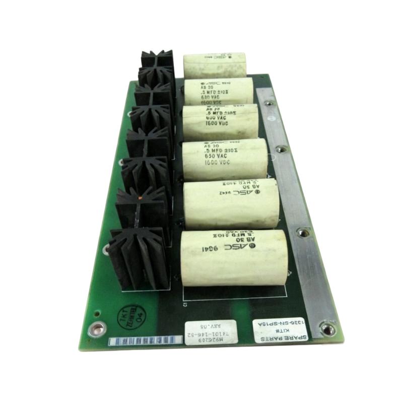
Allen Bradley 1336-SN-SP15A Repair Decision
A replacement PCB should be considered only after the surrounding circuit has been checked.
Before installing another board, verify the drive identification and application range. The current Rockwell product page identifies 1336-SN-SP15A as a 575 V PCB for 1336STEF applications and lists 300–650 HP, while the older spare-parts documentation lists the part for 300–800 HP A21–A23 configurations.
This difference makes catalog-number verification important when servicing legacy equipment.
Do not substitute a visually similar snubber PCB without confirming compatibility.
1336-SN-SP15A Real Field Troubleshooting Case
In one repair case, a 1336STEF drive repeatedly produced an inverter fault after a snubber PCB had been replaced.
The first assumption was that the replacement PCB had failed. We compared the replacement position with the other snubber positions and inspected the surrounding power components. The PCB itself showed no obvious manufacturing defect.
The diagnostic focus then shifted to the inverter power stage. Thermal discoloration was found near the associated switching section.
The important observation was that the failure repeated under the same electrical operating condition. This made a random PCB defect less likely and indicated that the replacement board was being exposed to the same underlying abnormal condition.
The repair therefore required investigation of the inverter section rather than repeated snubber PCB replacement.
Allen Bradley 1336-SN-SP15A Commissioning After Repair
After the Fault Diagnosis and repair are complete, commissioning should be performed progressively.
Start with controlled energization and verify the drive's diagnostic state. Then test the inverter without immediately applying maximum process load.
Monitor:
Drive fault status
DC-bus behavior
Output current
Acceleration response
Abnormal heating
Audible electrical noise
Snubber PCB temperature and condition
If the original failure occurred during acceleration, reproduce the acceleration profile during the final test. A repair is not fully validated simply because the drive runs at zero or light load.
Allen Bradley 1336-SN-SP15A Troubleshooting Long-Tail Keywords
This Troubleshooting Guide addresses search terms including:
Allen Bradley 1336-SN-SP15A troubleshooting
1336-SN-SP15A inverter snubber fault
1336-SN-SP15A Fault Diagnosis
1336-SN-SP15A PCB failure
1336-SN-SP15A repair procedure
1336-SN-SP15A 1336STEF fault
Allen Bradley inverter snubber troubleshooting
1336-SN-SP15A 575 V drive fault
1336-SN-SP15A replacement troubleshooting

