GE IS210AEDBH3ACC Bridge Interface Board Installation Guide
Time:2026-08-24 Browse: 20
The GE IS210AEDBH3ACC Bridge Interface Board should be installed with careful attention to board identification, connector condition, mounting position, and control-system configuration. A reliable installation is not simply a matter of replacing the PCB; the communication path and system response must also be verified during commissioning.
GE IS210AEDBH3ACC Installation Preparation
Before installing the GE IS210AEDBH3ACC, record the part number, board revision, cabinet location, and existing cable connections. Compare the replacement board with the original assembly before removing the existing unit.
Prepare the following information:
Board part number and revision
Rack or mounting position
Connector identification
Existing cable routing
Related control modules
Current system configuration
Existing diagnostic alarms
Use appropriate ESD protection when handling the board. Avoid touching connector contacts and exposed electronic components during installation.
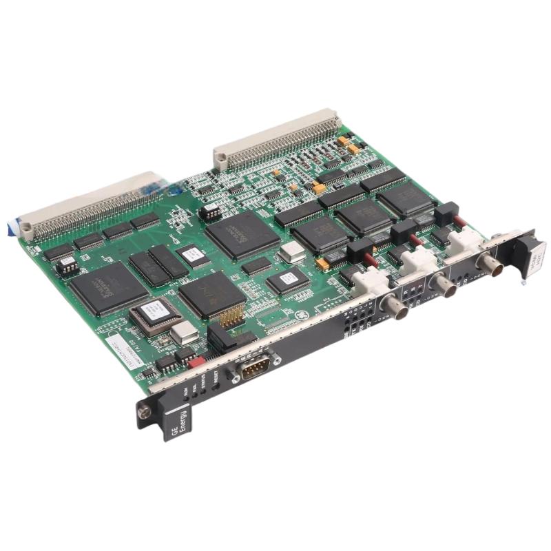
GE IS210AEDBH3ACC Bridge Interface Board Mounting
With the control system safely isolated, inspect the mounting position before inserting the board. Check for damaged connectors, loose hardware, contamination, overheating marks, or mechanical interference.
The board should enter the mounting position smoothly. If abnormal resistance is encountered, stop the installation rather than forcing the PCB into place. A damaged connector can create intermittent communication faults that are difficult to identify after the cabinet is energized.
Verify that each cable is returned to its original position. Photographing the existing wiring before removal is a practical field method when several similar connectors are present.
GE IS210AEDBH3ACC Wiring and Interface Inspection
Connector condition is particularly important for a bridge interface board because a poor electrical connection can produce symptoms that resemble an internal PCB failure.
During installation, inspect for:
Loose connector engagement
Bent or damaged contacts
Cable strain
Contamination
Signs of overheating
Damaged locking mechanisms
Incorrect cable routing
After reconnecting the cables, check that each connection is mechanically secure.
A common field mistake is to replace the board while leaving the original connector problem untouched. If the same communication fault remains after replacement, the connector and external wiring should become immediate suspects.
GE IS210AEDBH3ACC Setup and System Configuration
Once the physical installation is complete, verify the System Configuration before returning the control system to normal operation.
Compare the installed hardware with the engineering documentation and confirm that the expected control-system architecture is present.
The Setup review should include:
Hardware identification
Board position
Communication assignments
Connected modules
Application configuration
Diagnostic status
Software and hardware revision compatibility
Do not assume that a replacement PCB automatically resolves a configuration mismatch. Hardware installation and software configuration should be treated as two separate commissioning tasks.

GE IS210AEDBH3ACC Commissioning and Functional Verification
During Commissioning, first confirm that the controller starts normally and that no new diagnostic alarms appear.
Then verify the communication path and associated control functions. Monitor the system long enough to determine whether the board remains stable under normal operating conditions.
A practical commissioning record should include the measured supply condition, board identification, connector status, active diagnostics, communication status, and functional test result.
In one field replacement case, the new board powered up normally, but several downstream status signals remained unavailable. The board was removed from suspicion after confirming that it was correctly installed and recognized by the control system. Further inspection found that one connector had not been fully engaged. After correcting the connection, the missing signals returned.
The important field lesson is that successful PCB replacement does not necessarily mean successful system commissioning.
GE IS210AEDBH3ACC Installation Validation
The installation can be considered complete only after the complete signal path has been checked.
Verify that:
The correct IS210AEDBH3ACC board is installed
All connectors are secure
The control system starts normally
Expected communication is restored
No abnormal board-related alarms remain
Associated control functions operate correctly
The final hardware configuration is documented
This approach reduces the risk of returning a partially commissioned control system to service.
GE IS210AEDBH3ACC Installation Long-Tail Keywords
This Installation Guide is useful for searches related to GE IS210AEDBH3ACC installation, GE IS210AEDBH3ACC bridge interface board replacement, GE IS210AEDBH3ACC setup, GE IS210AEDBH3ACC commissioning, GE IS210AEDBH3ACC wiring, GE IS210AEDBH3ACC system configuration, and GE IS210AEDBH3ACC control system installation.
For field engineers, the most reliable installation method is to verify the PCB, inspect the physical interface, restore the configuration, and confirm system operation before completing the job.

