GE IS210AEDBH3ACC Bridge Interface Board Communication Fault Troubleshooting
Time:2026-08-24 Browse: 22
GE IS210AEDBH3ACC communication faults should be diagnosed by tracing the affected signal path rather than immediately assuming that the bridge interface board has failed. When communication is lost or associated control signals become unavailable, the fault may originate from the board, connector, external wiring, configuration, or another control-system component.
GE IS210AEDBH3ACC Communication Fault Symptoms
A problem involving the GE IS210AEDBH3ACC may appear as intermittent communication, missing status information, unexpected system alarms, unavailable downstream signals, or abnormal initialization after a controller restart.
The first diagnostic question should be whether the problem affects one communication path or several functions at the same time.
If only one device or signal is affected, inspect that local path first. If multiple dependent functions fail simultaneously, investigate the common bridge interface, power, communication path, and system configuration.
GE IS210AEDBH3ACC Fault Diagnosis Based on Failure Pattern
The timing and distribution of the fault provide more useful information than the alarm description alone.
For example:
Fault appears immediately after startup: check configuration and initialization.
Fault occurs after a board replacement: check installation and connector seating.
Fault appears intermittently during machine operation: inspect wiring, vibration, temperature, and power stability.
Several communication functions fail together: investigate the common interface.
One downstream signal remains abnormal: investigate the individual device or cable.
This method helps prevent unnecessary replacement of an expensive control PCB.
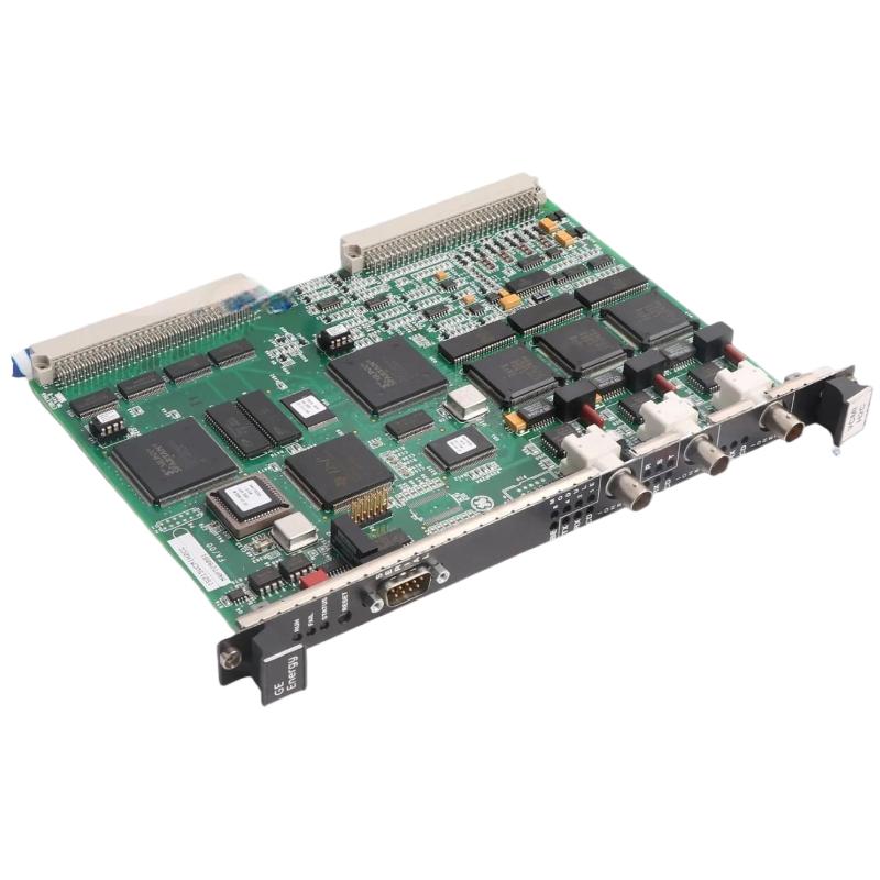
GE IS210AEDBH3ACC Troubleshooting: Physical Interface Checks
Before performing extensive software Fault Diagnosis, inspect the physical communication path.
Check the board and associated connections for:
Loose connectors
Damaged contacts
Cable movement
Incorrect cable routing
Contamination
Heat damage
Mechanical stress
Poor connector engagement
In industrial cabinets, vibration can gradually loosen a connection even when the system initially passes commissioning.
A useful field practice is to compare the affected connection with an equivalent known-good connection. Differences in connector engagement, cable condition, or termination can provide a strong diagnostic clue.
GE IS210AEDBH3ACC Bridge Interface Board Fault Investigation
If the physical connections appear normal, examine the system-level diagnostic information.
Record the controller operating state, affected communication channels, alarm timing, and behavior after a controlled restart.
Avoid repeatedly resetting the system before recording the original fault condition. A restart may temporarily restore communication while removing useful evidence about the original failure.
During Fault Diagnosis, change only one condition at a time. This makes it possible to determine whether the observed improvement actually came from the corrective action.
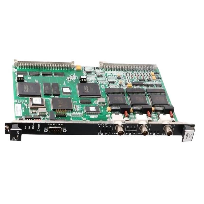
GE IS210AEDBH3ACC Communication Troubleshooting Field Case
In one field troubleshooting case, several communication-related alarms appeared after a control cabinet restart. Because the alarms involved multiple downstream functions, the initial suspicion was the bridge interface board.
The engineer first confirmed that the controller itself was operating normally. The board position and configuration were then checked, followed by a physical inspection of the interface connections.
The PCB was correctly installed and showed no obvious abnormality. However, one connector did not have the same mechanical engagement as the corresponding connections. After reseating and securing the connector, the affected communication signals returned during the next startup test.
The repair did not require replacing the IS210AEDBH3ACC. The actual fault was in the interface connection.
This is a typical industrial Troubleshooting lesson: when several functions disappear together, investigate the common signal path before condemning the PCB.
GE IS210AEDBH3ACC Repair and Replacement Decision
Board replacement should normally be considered only after external causes have been eliminated.
A replacement decision becomes stronger when:
Wiring and connectors have been verified
System Configuration is correct
The fault remains after external corrections
Diagnostic evidence points toward the board
The fault can be associated specifically with the board
A compatible known-good board restores normal operation
Before replacing the IS210AEDBH3ACC, document the original alarm condition and affected functions. After replacement, repeat the same operating test and compare the results.
This creates a clear before-and-after basis for Fault Diagnosis instead of relying on a simple "alarm disappeared" conclusion.
GE IS210AEDBH3ACC Troubleshooting Long-Tail Keywords
This troubleshooting article covers long-tail searches including GE IS210AEDBH3ACC troubleshooting, GE IS210AEDBH3ACC communication fault, GE IS210AEDBH3ACC fault diagnosis, GE IS210AEDBH3ACC bridge interface failure, GE IS210AEDBH3ACC communication problem, GE IS210AEDBH3ACC repair, GE IS210AEDBH3ACC board replacement, GE IS210AEDBH3ACC intermittent fault, and GE IS210AEDBH3ACC control system troubleshooting.
For this type of control-system fault, the most reliable approach is to follow the failure boundary, verify the physical interface, confirm the System Configuration, and only then decide whether the bridge interface board itself requires replacement.

