Allen-Bradley MPL-B310P-RJ74AA Servo Motor Installation Guide
Time:2026-09-03 Browse: 18
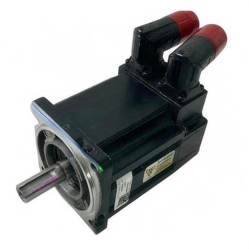
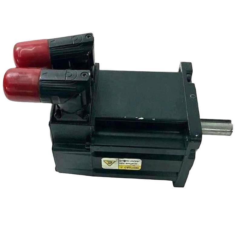
The Allen-Bradley MPL-B310P-RJ74AA servo motor is a low-inertia rotary servo motor designed for 460/480 V AC motion applications, with a 5000 rpm maximum speed, resolver feedback, keyed shaft, right-angle SpeedTEC DIN connector, and an integral 24 V DC brake. For a reliable installation, the most important work is not simply mounting the motor—it is matching the motor, feedback system, brake circuit, drive configuration, mechanical load, and commissioning parameters before the first motion command.
Allen-Bradley MPL-B310P-RJ74AA Servo Motor Installation Requirements
Before installing the MPL-B310P-RJ74AA, confirm the exact catalog number on the motor nameplate. This matters because the MPL-B310P family contains versions with different feedback technologies and connector configurations. The RJ74AA version uses resolver feedback and a 24 V DC brake, so the drive-side configuration must correspond to that feedback arrangement.
The motor uses a 100 mm frame and IEC metric flange mounting. It has a keyed shaft and a right-angle SpeedTEC DIN connector that can be rotated for cable orientation. Rockwell Automation identifies the motor as part of the MP-Series MPL low-inertia brushless servo motor family.
Before mechanical installation, inspect the shaft, flange, connector, cable entry, and mounting surface. Look for shipping damage, contamination, loose hardware, or signs of impact. Do not rotate the shaft aggressively while the motor is disconnected from the drive if the connected machine could impose an unexpected mechanical load.
A practical commissioning rule is simple: verify the motor identity before connecting power.
MPL-B310P-RJ74AA Mechanical Setup and Mounting
The motor should be mounted on a rigid, accurately machined surface. A servo motor can generate rapid acceleration and deceleration, so a mounting surface that appears adequate during static inspection may still produce vibration when the machine begins motion.
Align the motor shaft carefully with the driven equipment. Avoid using the servo motor shaft to compensate for poor machine alignment. Excessive radial or axial loading can shorten bearing life and can also introduce position errors that may initially look like an electrical feedback problem.
For coupling applications, check the coupling manufacturer's allowable misalignment values rather than assuming that the coupling can absorb large installation errors.
The MPL-B310P-RJ74AA uses a keyed shaft. Make sure the key and coupling are correctly fitted and that the coupling is properly secured. Do not hammer directly on the motor shaft during installation.
In field commissioning, unusual mechanical noise immediately after installation is a useful warning. If the motor produces a repeating vibration pattern even at low speed, it is worth checking shaft alignment before changing servo tuning parameters.
MPL-B310P-RJ74AA Power and Brake Wiring
The MPL-B310P-RJ74AA is a high-voltage AC servo motor intended for the appropriate Allen-Bradley motion drive system. Rockwell Automation lists the motor's armature voltage as 460 V and specifies a 24 V DC brake option.
Power wiring should be completed according to the applicable Rockwell Automation motor and drive documentation. The motor cable must be suitable for the drive output and installation environment, and grounding should be treated as part of the motion system rather than as an optional accessory.
The brake requires particular attention. A holding brake is not a substitute for a properly engineered safety system. Before releasing or energizing the brake, determine how the driven load behaves when motor torque disappears.
For a vertical axis, for example, the machine may begin to move under gravity when the brake releases. The commissioning sequence should therefore verify brake timing and load behavior at low risk before normal production operation.
MPL-B310P-RJ74AA Resolver Feedback Setup
Resolver feedback is one of the most important characteristics of this particular model. Do not configure the drive as though the motor were equipped with an encoder simply because another MPL-B310P variant may use an encoder.
The feedback connection should be inspected for correct termination, connector engagement, shielding, and cable routing. Keep feedback wiring separated from high-current switching conductors where the machine design allows.
If the motor is mechanically installed but the drive cannot establish valid feedback, do not immediately assume that the resolver inside the motor has failed.
A better diagnostic sequence is:
Check the connector.
Check cable continuity.
Check drive feedback configuration.
Check shielding and grounding.
Check whether the feedback fault appears immediately at power-up or only after motion begins.
This distinction can save considerable troubleshooting time.
A fault that appears immediately after connection usually points toward configuration, wiring, connector, or feedback integrity. A fault that appears only when the motor accelerates may require additional investigation of electrical interference, cable routing, mechanical movement, or drive configuration.
Allen-Bradley MPL-B310P-RJ74AA Drive System Configuration
The servo motor cannot be commissioned correctly as an isolated component. The motor, drive, motion controller, feedback device, brake circuit, and mechanical load form one system.
The System Configuration should therefore be reviewed before applying a motion command.
Confirm the motor catalog selection, feedback type, voltage class, rated speed, brake configuration, and applicable motor data. The MPL-B310P-RJ74AA is specified for 5000 rpm maximum speed and 1.58 N·m continuous output torque in commonly published specifications.
Do not copy configuration values from a visually similar motor. Two motors from the same MPL family can differ in feedback and shaft configuration.
This is especially important when replacing an existing motor. The physical mounting may appear identical while the feedback technology or electrical configuration is different.
MPL-B310P-RJ74AA Initial Power-Up and Commissioning
The first power-up should be treated as a controlled test rather than a production start.
With the machine secured, verify that personnel are clear of moving parts and that the load cannot create an unsafe condition. Confirm that the motor is correctly connected and that the drive reports normal status before enabling motion.
Start with a low-risk motion command.
Observe whether the motor rotates in the expected direction.
Listen for abnormal mechanical noise.
Watch the drive for feedback or overcurrent faults.
Check whether the motor accelerates smoothly.
If the motor immediately trips, stop the test rather than repeatedly resetting the drive.
Repeated resets can hide the original failure pattern. The first fault is usually more useful than the fifth reset.
During commissioning, record useful values such as command speed, actual speed, acceleration behavior, drive current, fault code, and feedback status. These values create a baseline for future Troubleshooting.
MPL-B310P-RJ74AA Servo Motor Motion Validation
After basic operation has been established, increase the operating speed gradually.
A practical commissioning test can begin at approximately 10–20% of the intended operating speed. At each stage, observe the actual speed response and listen for changes in vibration or mechanical noise.
For example, if a motor runs smoothly at 500 rpm but develops strong vibration around 1500 rpm, do not immediately change the servo gain. First determine whether the vibration follows motor speed, machine resonance, coupling alignment, or load characteristics.
This distinction is important.
A control-loop problem often changes with tuning parameters and command dynamics. A mechanical resonance may occur repeatedly around a particular speed regardless of small control adjustments.
Allen-Bradley MPL-B310P-RJ74AA Installation Validation
A completed installation should leave behind more than a motor that turns.
The final validation should confirm:
The motor catalog number matches the engineering configuration.
The resolver feedback is correctly recognized.
The brake operates as intended.
The motor rotates in the correct direction.
The mechanical coupling is secure.
The motor reaches the required speed without abnormal vibration.
The drive does not generate recurring faults.
The machine can stop in the required operating and safety conditions.
The commissioning data should be recorded for maintenance reference.
Rockwell Automation lists the MPL-B310P-RJ74AA as an active-mature MP-Series MPL servo motor and identifies its country of origin as Mexico.
Long-Tail Keywords for MPL-B310P-RJ74AA Installation
Common search terms associated with this installation work include Allen-Bradley MPL-B310P-RJ74AA Installation Guide, MPL-B310P-RJ74AA servo motor setup, MPL-B310P-RJ74AA commissioning, Allen-Bradley resolver servo motor installation, MPL-B310P-RJ74AA brake wiring, MPL-B310P-RJ74AA System Configuration, and Allen-Bradley MP-Series servo motor commissioning.
These terms describe different stages of the same engineering task: correctly integrating the servo motor into a complete motion control system.
Field Commissioning Experience with MPL-B310P-RJ74AA
In one typical servo commissioning situation, the motor itself may be suspected because the axis does not move correctly after replacement. However, the more useful engineering approach is to separate the problem into three layers: electrical connection, feedback, and mechanical load.
If the drive recognizes the resolver but produces an overcurrent condition when motion begins, attention should move toward the power circuit, mechanical load, coupling, and motor phase relationship rather than immediately replacing the resolver.
If the drive cannot establish feedback before motion begins, mechanical alignment is unlikely to be the first suspect. Feedback wiring and System Configuration become much more relevant.
This fault-isolation method is particularly useful with replacement MPL motors because many catalog variants have similar mechanical dimensions while differing in feedback technology.
A good Allen-Bradley MPL-B310P-RJ74AA Installation Guide therefore should not end with mounting instructions. Successful Setup and Commissioning depend on proving that the motor, drive, resolver feedback, brake, and machine behave as one controlled system.

