Schneider LTMR27MFM Motor Controller Installation Guide
Time:2026-09-04 Browse: 16
The Schneider Electric LTMR27MFM motor controller is a TeSys T motor management controller for 3-phase AC motor applications, providing motor protection, monitoring, control, and Modbus communication. It accepts a 100–240 V AC control supply and covers a motor current measurement range of 1.35–27 A. For a reliable installation, the critical points are correct current-range configuration, control wiring, motor protection settings, and Modbus communication setup rather than simply mounting the controller in the panel.
Schneider LTMR27MFM Motor Controller Application
The LTMR27MFM belongs to the TeSys T Motor Management System. It is intended for equipment monitoring and control and provides protection functions such as overload, phase failure, phase imbalance, locked rotor, earth leakage, and thermal protection. The controller also supports fault recording, trip history, motor operating statistics, and diagnostic information.
A useful installation principle is to treat the LTMR27MFM as the monitoring and control center of the motor feeder. The controller needs correct information about motor current and operating conditions before its protection functions can work as intended.
The model is specifically the Modbus version. Its communication interface uses two-wire RS-485, with addressing from 1 to 247 and transmission rates from 1.2 to 19.2 kbit/s.
LTMR27MFM Installation Preparation
Before wiring, verify the controller reference against the electrical design. The LTMR27MFM is rated for a 100–240 V AC, 50/60 Hz control supply, with an allowable supply range of approximately 93.5–264 V AC. Its motor current measurement range is 1.35–27 A.
The first practical check should therefore be the motor full-load current.
If the connected motor is outside the controller's applicable current range, changing software parameters will not turn the LTMR27MFM into a suitable controller.
Also inspect the panel installation conditions. Leave sufficient space for wiring, terminal access, communication cables, and maintenance. Keep RS-485 communication wiring away from high-noise power conductors where the panel layout permits.
Before making connections, isolate the equipment and verify the absence of hazardous voltage according to the site's electrical safety procedure.
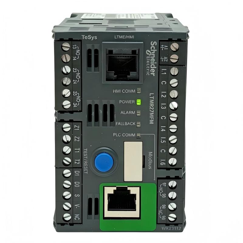
Schneider LTMR27MFM Power and Motor Wiring
The control supply and motor measurement circuit should be wired according to the applicable TeSys T documentation and the machine electrical design.
Pay particular attention to the current-measuring arrangement. The controller relies on measured motor current for protection and monitoring. A wiring error affecting current measurement can result in misleading overload or phase-related information even though the controller itself is functioning.
After wiring, compare the measured phase currents under a stable motor load.
For example, if a motor normally operates around 8 A per phase but the controller displays a significantly different value on one phase, do not immediately change the overload setting. First check the current path, terminal connections, phase arrangement, and measurement setup.
The purpose of commissioning is to prove the measurement chain—not simply to make the motor start.
LTMR27MFM Motor Protection Setup
The protection settings should be based on the actual motor nameplate and application.
The LTMR27MFM provides multiple protection functions, including overload, phase failure, phase imbalance, locked rotor, earth leakage, thermal overload, and load fluctuation monitoring.
In a practical installation, avoid setting protection values simply because they worked on another motor.
A 15 kW pump motor and a conveyor motor with different starting characteristics may require different protection behavior even if their nominal currents are similar.
During Setup, record the motor rated current, starting characteristics, expected operating load, and required trip behavior. These values provide a reference when Troubleshooting is later required.
Schneider LTMR27MFM Modbus Communication Setup
Communication should be commissioned separately from the motor protection functions.
The LTMR27MFM uses Modbus over two-wire RS-485. The interface supports addresses 1–247 and communication speeds from 1.2 to 19.2 kbit/s. The controller can provide communication through an RJ45 interface or terminal connection using shielded twisted-pair wiring.
A practical commissioning configuration can use an address such as 4, 19,200 baud, and even parity, provided these settings match the Modbus master. Schneider's TeSys T Modbus Quick Start documentation uses address 4, 19,200 baud, and even parity in its example configuration.
Do not assume that communication failure means the controller is defective.
First compare:
Modbus slave address.
Baud rate.
Parity.
RS-485 polarity.
Cable termination.
Master configuration.
Communication cable continuity.
A single incorrect parameter can make a healthy LTMR27MFM appear offline.
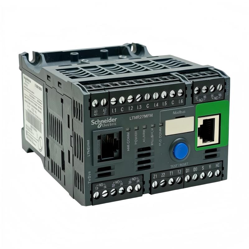
LTMR27MFM System Configuration and Commissioning
The System Configuration should be checked from the motor side outward.
First verify that the motor current information is correct.
Then confirm protection settings.
Next verify the control logic.
Finally establish Modbus communication with the PLC or supervisory system.
This order makes commissioning easier because each layer can be tested independently.
For example, if the LTMR27MFM correctly measures current and responds to local control but the PLC cannot read its status, the motor control section is probably not the first place to investigate. Attention should move toward Modbus configuration and RS-485 wiring.
The TeSys T system can be controlled through its terminal strip, HMI, or communication port, making it suitable for integration into automated motor-control architectures.
Schneider LTMR27MFM First Motor Start
The first motor start should be treated as a measurement test.
Before energizing the motor, confirm that the mechanically driven equipment is ready for operation and that the correct motor is connected.
During the first start, observe the starting current and the duration of acceleration.
The controller maintains motor history information including motor starts, operating time, last-start current ratio, and last-start duration.
These values are useful during commissioning because they establish a baseline.
For example, if the motor normally reaches stable operation after 2 seconds but the starting period suddenly increases to 6 seconds after a mechanical change, that difference may indicate increased load or a developing mechanical problem.
The controller should therefore be used not only as a protection device but also as a source of diagnostic information.
LTMR27MFM Installation Validation
A successful installation should demonstrate that the entire motor management loop works correctly.
Check that the controller powers up normally.
Confirm that motor current is measured correctly.
Verify that the protection settings correspond to the motor.
Test the required control commands.
Confirm the motor starts and stops correctly.
Verify Modbus communication with the PLC.
Check that relevant status and fault information reaches the control system.
Review the motor history after commissioning.
A useful field practice is to save the initial configuration and commissioning measurements. When a fault occurs several months later, these baseline values can help determine whether the problem is new or has gradually developed.
Schneider LTMR27MFM Field Commissioning Example
In one typical commissioning situation, the motor starter operated correctly from the local control circuit, but the PLC continued to show an unavailable motor status.
The first assumption was a controller communication failure.
However, the LTMR27MFM itself was operating normally and its local motor measurements were available. The diagnostic process therefore moved toward the Modbus layer.
The slave address in the controller was found to differ from the address configured in the PLC.
After the address was corrected, communication was restored without replacing the controller or changing the motor wiring.
This is a common engineering lesson: when an intelligent motor controller works locally but disappears from the automation network, separate the motor-control problem from the communication problem before replacing hardware.
LTMR27MFM Installation Guide Long-Tail Keywords
Relevant long-tail search terms include Schneider LTMR27MFM Installation Guide, LTMR27MFM motor controller setup, LTMR27MFM commissioning, Schneider TeSys T motor controller wiring, LTMR27MFM Modbus setup, LTMR27MFM System Configuration, LTMR27MFM motor protection settings, Schneider LTMR27MFM RS-485 communication, and LTMR27MFM motor management controller installation.
The LTMR27MFM is a specialized TeSys T controller, so correct installation depends on matching the motor's electrical characteristics, protection requirements, and communication architecture rather than treating the device as a conventional motor starter.
Schneider LTMR27MFM Commissioning Checklist
Before handing the motor feeder over to production, verify the following:
The LTMR27MFM model matches the project specification.
The control supply is within the required range.
The motor current is within the 1.35–27 A measurement range.
Current measurement is stable and plausible.
Protection parameters match the motor application.
Control commands operate correctly.
Fault and trip information can be identified.
Modbus communication is stable.
The PLC receives the required motor status information.
Initial motor operating data has been recorded.
The LTMR27MFM is listed by Schneider Electric as a TeSys T motor controller with 1.35–27 A measurement capability, 100–240 V AC supply, Modbus communication, six logic inputs, and three logic outputs.

