Allen-Bradley MPL-B320P-SJ72AA Servo Motor Installation Guide: Setup & Commissioning
Time:2026-09-07 Browse: 18
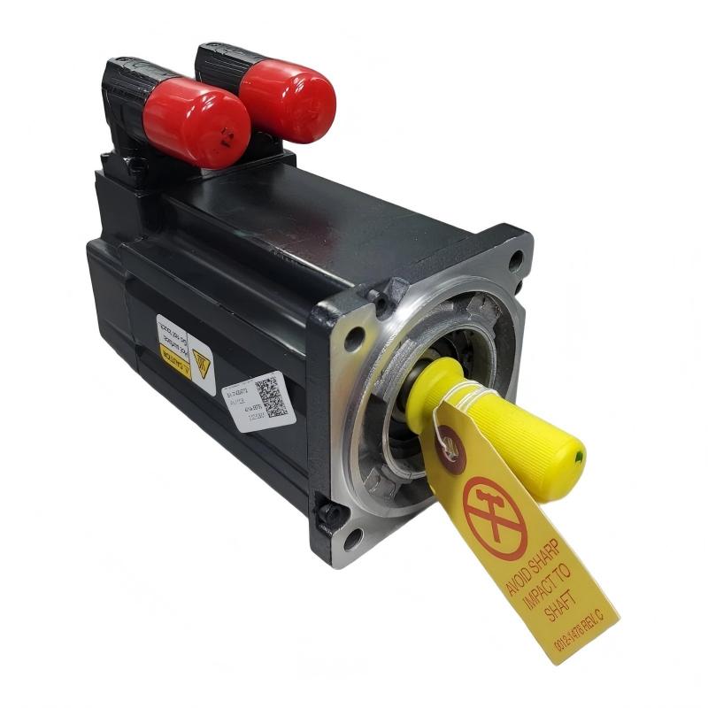
Allen-Bradley MPL-B320P-SJ72AA servo motor installation depends on correct mechanical mounting, motor-drive compatibility, feedback wiring, and encoder configuration. The MPL-B320P-SJ72AA is a low-inertia brushless servo motor with a 100 mm frame, 50.8 mm magnet stack, 5000 RPM rated speed, keyed shaft, single-turn high-resolution encoder, right-angle SpeedTEC DIN connector, and no brake.
Allen-Bradley MPL-B320P-SJ72AA Servo Motor Installation Requirements
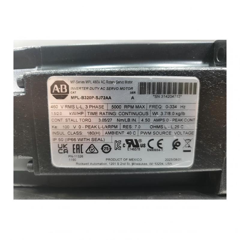
Before starting the Installation Guide, verify the motor nameplate against the motion-system configuration. The MPL-B320P-SJ72AA belongs to the MP-Series MPL family and is specified for the 460 V class. Its single-turn high-resolution feedback device must also be correctly recognized by the selected servo drive.
The motor uses an IEC metric mounting arrangement and free mounting holes. The shaft is keyed, so the coupling and driven load should be selected to match the shaft arrangement rather than forcing an incompatible hub onto the motor.
A practical installation check should include:
Motor catalog number and series verification
Servo drive compatibility
Correct motor power cable
Correct feedback/encoder cable
Mechanical coupling and shaft alignment
Protective grounding
Adequate cooling and clearance
Correct System Configuration in the motion controller
Do not energize the system simply because the motor can be mechanically mounted. Feedback identification and drive configuration are equally important parts of servo commissioning.
MPL-B320P-SJ72AA Mechanical Setup and Shaft Alignment
Mechanical alignment is one of the first areas I check when commissioning an MP-Series motor. A servo motor can appear electrically healthy while producing excessive following error because the load is misaligned.
Mount the MPL-B320P-SJ72AA firmly against a suitable IEC metric flange. Check that the mounting surface is clean and free from burrs. The shaft coupling should be installed without forcing the motor shaft sideways or axially.
For a keyed shaft, confirm that the key and coupling are correctly seated. Avoid using the motor shaft to pull a coupling into position. Excessive radial or axial loading can affect bearings and create vibration that may later be mistaken for an encoder or drive fault.
A useful field check is to rotate the coupled mechanism manually, where the machine design permits it. Resistance should remain reasonably consistent throughout one revolution.
Allen-Bradley MPL-B320P-SJ72AA Motor Wiring and Feedback Connection
The MPL-B320P-SJ72AA uses a right-angle SpeedTEC DIN connector that can be rotated through 180 degrees. This gives the installer some flexibility when routing the motor cable inside a compact machine.
During wiring, separate the power and feedback routing as required by the drive manufacturer's installation practices. Inspect connectors carefully for damaged contacts, contamination, loose locking mechanisms, or incorrect cable orientation.
The feedback connection deserves particular attention. This model uses a single-turn high-resolution encoder. A drive configured for a different feedback type may generate an encoder-related fault even though the motor power circuit is correct.
Before applying power, verify:
Motor power phases are correctly terminated.
Protective earth is properly connected.
Feedback connector is fully seated.
Cable shielding and grounding follow the drive requirements.
Motor and drive catalog data agree.
No brake wiring is expected, because this motor configuration has no brake.
MPL-B320P-SJ72AA Servo Drive Setup and System Configuration
The next stage is System Configuration in the motion-control software. The motor should be entered using the exact catalog number rather than a similar-looking MPL model.
This matters because nearby MPL variants can differ in feedback, shaft, connector, brake, or other configuration details. Selecting an approximate motor may allow the project to download while leaving incorrect motor characteristics in the axis configuration.
A good commissioning sequence is to verify the motor identity first, then confirm feedback, motor electrical data, scaling, direction, and operating limits.
For initial testing, use conservative speed and acceleration limits. The motor has a 5000 RPM rated speed, but that does not mean the machine should immediately be tested at its maximum speed.
Allen-Bradley MPL-B320P-SJ72AA Commissioning and Motion Validation
After the drive accepts the configuration, perform a controlled enable test with the load in a safe condition.
Watch the axis status while enabling the servo. The important question is not simply whether the motor turns. The commissioning engineer should confirm that commanded position, actual position, velocity feedback, and axis status behave consistently.
A useful field sequence is:
Enable the axis at low speed.
Command a small movement.
Check actual direction.
Compare commanded and actual position.
Listen for abnormal mechanical noise.
Check following error.
Increase speed gradually.
Repeat with the actual machine load.
If the motor immediately produces a large position error, do not compensate by increasing servo gains without investigation. Check the feedback path, mechanical coupling, axis direction, and load condition first.
Real-World MPL-B320P-SJ72AA Commissioning Check
In one typical servo commissioning situation, the motor passed the electrical startup check but produced noticeable mechanical vibration during the first low-speed movement. The initial assumption was an incorrect servo tuning value.
The better diagnostic approach was to stop increasing the gain and inspect the mechanical side. The coupling alignment was slightly offset, producing additional load variation during rotation. After correcting the alignment and repeating the low-speed test, the axis response became stable without aggressive tuning changes.
This is an important field lesson for MPL-B320P-SJ72AA installation: not every motion problem is a drive-parameter problem.
Allen-Bradley MPL-B320P-SJ72AA Installation Validation
A completed Installation Guide should end with functional validation rather than simply confirming that the motor runs.
Record the motor catalog number, drive configuration, feedback status, direction, operating speed, and relevant axis diagnostics. Check the motor and coupling after a controlled operating period for abnormal temperature, vibration, or noise.
The MPL-B320P-SJ72AA is a low-inertia servo motor intended for precise motion applications. Correct mechanical installation, encoder feedback, and System Configuration provide the foundation for reliable Setup / Commissioning and long-term servo performance.
Long-Tail Keywords for MPL-B320P-SJ72AA Servo Motor Installation
Allen-Bradley MPL-B320P-SJ72AA installation guide, MPL-B320P-SJ72AA servo motor setup, MPL-B320P-SJ72AA commissioning procedure, Allen-Bradley MPL servo motor wiring, MPL-B320P-SJ72AA encoder setup, MPL-B320P-SJ72AA servo drive configuration, MPL-B320P-SJ72AA installation and commissioning, Allen-Bradley MP-Series servo motor setup.

