Emerson A6500-UM Universal Measurement Card Installation Guide
Time:2026-09-08 Browse: 23
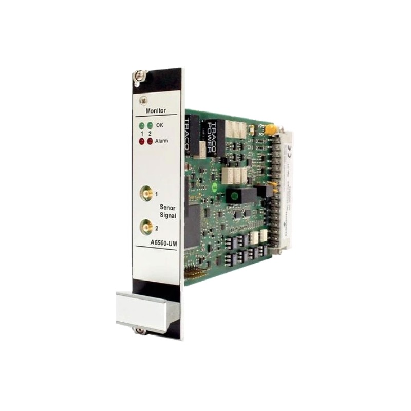
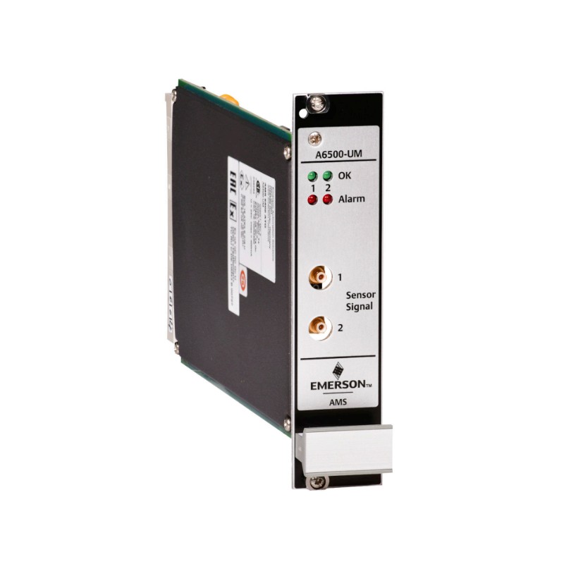
Emerson A6500-UM installation is mainly a matter of matching the measurement application, sensor wiring, rack slot, and Machine Studio configuration before putting the machinery protection channel into service. The A6500-UM is a two-channel Universal Measurement Card used in the AMS 6500 ATG machinery protection system, with support for sensor types including eddy-current, piezoelectric, seismic, Hall-effect, LVDT through the A6500-LC, and dynamic pressure sensors.
Emerson A6500-UM Measurement Card Installation Overview
The A6500-UM is installed as a plug-in card in an A6500-xR System Rack. Its two measurement channels can normally operate independently or be combined according to the selected measurement mode. Speed applications are an exception because both channels are used for speed measurement.
For a field installation, the important point is not simply getting the card physically into the rack. The sensor type, measurement function, input range, alarm behavior, current output, digital outputs, and Channel OK supervision must all agree with the actual machinery measurement chain.
The card uses the internal rack connection to exchange measurement data with the A6500-CC communication card. The A6500-CC provides the interface for configuration and communication with higher-level systems.
Emerson A6500-UM Installation Preparation
Before inserting the card, verify the following items:
A compatible A6500-xR System Rack
Correct A6500-UM card
Correct sensor and sensor cable
Required rack wiring and termination
A6500-CC Com Card for configuration
Machine Studio configuration software
USB or Ethernet connection to the communication card
Defined measurement range and alarm limits
The A6500-UM is a 100 × 160 mm Euro-card design with a 6 HP front plate and is intended specifically for the A6500-xR rack system.
A common commissioning mistake is to configure the software before confirming the physical sensor chain. This can make a wiring problem look like a configuration problem. A better field approach is to establish the physical measurement chain first and then validate the software parameters.
Emerson A6500-UM Rack Installation and Wiring
Select one of the available protection-card slots in the A6500-xR System Rack and prepare the slot wiring according to the required measurement application.
The A6500-UM installation procedure is straightforward: select the appropriate slot, connect the sensor and I/O wiring according to the measurement task, insert the card into the prepared slot, and secure the front-panel screws by hand. The card is designed to be hot-swappable, although any intervention in a machinery protection system should be evaluated carefully because incorrect work can affect machine protection.
Pay particular attention to the sensor connection. The A6500-UM does not use one universal electrical input range for every sensor type. Its signal-conditioning behavior changes according to the selected measurement application.
For example, eddy-current, piezoelectric, seismic, Hall-effect, and pressure measurements have different signal characteristics. Therefore, selecting the correct sensor type in System Configuration is part of the electrical commissioning process rather than an optional software setting.
Emerson A6500-UM Sensor Setup and System Configuration
After the card is installed, the next stage is the A6500-UM Setup in Machine Studio.
The configuration can be prepared offline or performed online through the A6500-CC Com Card. A typical configuration workflow is to connect a PC or laptop to the Com Card, open Machine Studio, select the A6500-UM, choose the required measurement application, enter the measurement parameters, and send the configuration to the card.
The configuration should reflect the actual field installation:
Sensor technology
Measurement type
Input channel assignment
Measurement range
Signal evaluation
Alarm limits
Channel OK behavior
Current output assignment
Digital output assignment
Speed or key-signal requirements where applicable
Do not use a previous configuration simply because the replacement card has the same model number. Two A6500-UM cards can have completely different measurement applications depending on the machinery protection requirement.
Emerson A6500-UM Commissioning and Signal Validation
A successful A6500-UM commissioning should verify both the measurement value and the health status of the channel.
The Channel OK function is particularly useful during commissioning. A healthy channel is represented by a valid Channel OK state, while a sensor fault, signal overload, or card-health problem can cause the channel to enter a not-OK condition. The current outputs can also be configured for 0/4–20 mA measurement transmission.
In a practical commissioning sequence, I would first confirm:
The A6500-UM is recognized by Machine Studio.
The selected application matches the installed sensor.
The sensor supply and signal are present.
Channel OK is healthy.
The displayed measurement is physically reasonable.
Alarm limits behave as expected.
The assigned digital outputs respond correctly.
The analog output corresponds to the configured measurement range.
The A6500-CC communication path provides valid status and measurement data.
This order matters. If the sensor signal is already invalid, testing Modbus communication first usually adds another layer of uncertainty instead of isolating the actual problem.
Emerson A6500-UM Installation Field Case
A useful commissioning scenario is a newly installed vibration channel that reports Channel not OK immediately after startup.
The first assumption should not be that the A6500-UM card is defective. The A6500-UM monitors several conditions independently, including sensor status, signal validity, and card health. Emerson's Machine Studio documentation specifically shows a Channel not OK condition caused by missing input connections.
The engineering approach is therefore:
Card recognized → configuration verified → sensor connection checked → signal level checked → Channel OK evaluated.
If the channel becomes healthy after the sensor connection is restored, replacing the measurement card would have been unnecessary.
This is an important field habit with machinery monitoring equipment: diagnose the complete measurement chain before condemning the electronics.
Emerson A6500-UM Installation Validation
The final validation should be performed with the machine in a controlled operating condition.
Check the measured vibration, displacement, velocity, acceleration, speed, position, or pressure value against an expected process condition. For dynamic measurements, compare the trend with an established baseline rather than relying only on whether the number looks plausible.
The A6500-UM provides self-checking functions for hardware, power input, temperature, sensor, and cable conditions. This makes the Channel OK information an important part of commissioning rather than merely an alarm indication.
Once the measurement values, Channel OK status, alarm outputs, and communication data all agree, the Emerson A6500-UM Setup / Commissioning process can be considered complete.
Long-Tail Keywords for Emerson A6500-UM Installation
Natural search terms associated with this Installation Guide include:
Emerson A6500-UM installation guide, Emerson A6500-UM Universal Measurement Card installation, A6500-UM setup procedure, A6500-UM commissioning guide, A6500-UM sensor wiring, A6500-UM Machine Studio configuration, A6500-UM Channel OK commissioning, A6500-UM measurement card setup, AMS 6500 A6500-UM installation, and Emerson A6500-UM system configuration.
The most reliable installation strategy is simple: establish the physical sensor chain first, configure the measurement application second, and validate the complete protection path last.

