Emerson A6500-UM Universal Measurement Card Troubleshooting Guide
Time:2026-09-08 Browse: 20
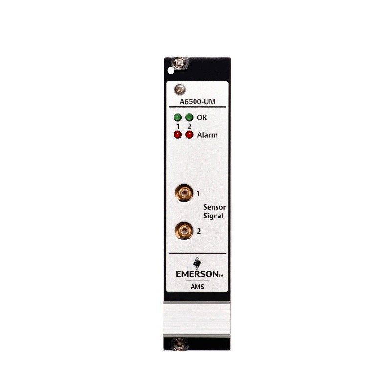
Emerson A6500-UM Channel not OK faults should be diagnosed from the sensor chain toward the measurement card, not by immediately replacing the card. The A6500-UM separates channel errors from card errors, allowing an engineer to distinguish sensor faults, signal overload, temperature conditions, and internal card problems through Channel OK supervision and Machine Studio.
Emerson A6500-UM Channel Not OK Fault Symptoms
A typical A6500-UM fault appears as a Channel not OK indication for one measurement channel. Depending on the fault condition, the front-panel Channel OK LED may be off, while Machine Studio provides more detailed status information.
The important diagnostic flags include:
Sensor
Signal
Card health
Bypass
Channel OK status
A sensor fault points toward the measuring chain. A signal fault indicates that the input signal has exceeded the valid range. A card-health fault points toward the electronics themselves.
This distinction is valuable because the same visible symptom — a failed channel — can have completely different causes.
Emerson A6500-UM Sensor Fault Diagnosis
When Machine Studio reports a sensor-related Channel OK fault, start at the sensor rather than the A6500-UM PCB.
Inspect:
Sensor connector
Field wiring
Cable continuity
Sensor supply
Sensor type
Configuration parameters
Termination and load components where required
For Hall-effect applications, for example, Channel OK supervision can depend on the specified load-resistor arrangement. Emerson documents a case where additional load resistance is required to detect an open sensor input.
This is exactly the type of fault that can be misdiagnosed as an electronics failure. The card may be functioning correctly while the measurement chain is electrically incomplete.
Emerson A6500-UM Signal Overload Troubleshooting
A different fault pattern occurs when the sensor is connected but the input signal is outside the valid measurement range.
The A6500-UM identifies an overload when its input amplifier is overdriven. Machine Studio can therefore show the channel as faulty even though the sensor cable is physically connected.
The diagnostic logic should be:
Sensor connected → signal present → signal within configured range → Channel OK restored.
If the signal remains excessive, check the actual sensor output and compare it with the selected sensor type and measurement configuration.
For example, a sensor may be mechanically healthy but electrically unsuitable for the selected input configuration. Changing the sensor or measurement application without checking the actual signal can hide the root cause rather than correct it.
Emerson A6500-UM Fault Diagnosis Using Channel OK
Channel OK should be treated as a diagnostic tree rather than a simple green/red indication.
A healthy channel has no sensor, signal, or card-health fault. If the Sensor flag is active, investigate the sensor and wiring. If Signal indicates overload, investigate the input level and measurement range. If Card health indicates a fault, move the investigation toward the A6500-UM hardware and system condition.
This approach prevents unnecessary card replacement.
The same diagnostic philosophy applies when the two channels behave differently. If Channel 1 operates normally while Channel 2 reports a sensor fault, the probability of a complete system-level power problem is lower. The investigation should concentrate on the Channel 2 measuring chain first.
Emerson A6500-UM False Measurement Troubleshooting
Not every A6500-UM problem produces a clear Channel not OK message.
A more difficult case is a channel that remains healthy but reports an implausible measurement.
For example, a vibration channel may remain within its electrical input range while the measured amplitude is much higher than the expected machine condition. In this situation, the Channel OK state alone does not prove that the measurement is correct.
The investigation should compare:
sensor signal → configured measurement type → scaling → displayed engineering value → analog output.
If the raw signal is reasonable but the engineering value is incorrect, review System Configuration and measurement scaling before replacing the card.
The A6500-UM supports different measurement evaluations, including displacement, velocity, acceleration, position, speed, and pressure-related measurements depending on the selected application.
Emerson A6500-UM Communication Fault Diagnosis
A communication problem should be separated from a measurement-channel problem.
The A6500-UM exchanges measurement information with the A6500-CC Com Card through the internal RS-485 bus. The Com Card then provides Modbus RTU, Modbus TCP/IP, and configuration access.
If the local A6500-UM measurement is correct in Machine Studio but the host system does not receive the expected value, investigate the communication path before replacing the measurement card.
A useful diagnostic split is:
Local measurement correct + host value missing = communication-side investigation.
Local measurement incorrect + Channel OK fault = measurement-chain investigation.
This distinction can significantly reduce troubleshooting time.
Emerson A6500-UM Card Health Fault Troubleshooting
A genuine card-health fault deserves a different approach.
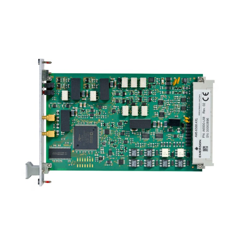
Check the card status, system-rack condition, configuration, and temperature information. The A6500-UM includes self-checking for hardware, power input, hardware temperature, sensor, and cable conditions.
If the card reports an internal fault while the sensor and wiring have already been verified, compare the behavior with another known-good channel where practical.
Do not immediately transfer the configuration and declare the replacement successful. After replacement, confirm that the new card is recognized, the correct configuration is loaded, Channel OK is restored, and the measurement value agrees with the previous operating baseline.
Emerson A6500-UM Troubleshooting Field Case
Consider a field situation in which Channel 2 suddenly changes to Channel not OK while Channel 1 continues operating normally.
The first observation suggests that the rack supply and common system functions are probably still operating. The next diagnostic point is the Channel OK detail in Machine Studio.
If the Sensor flag is active but Card health remains normal, the fault is more likely to be in the Channel 2 sensor chain than in the A6500-UM electronics. Emerson's troubleshooting documentation explicitly directs the engineer to check the sensor, wiring, and connections when the Sensor fault flag is active.
After restoring the sensor connection, the channel should be monitored until the status returns to normal. Emerson documents waiting behavior for several sensor-supervision conditions; for example, some channel errors reset after the measured value returns to the acceptable range and a waiting period has elapsed.
The important engineering lesson is that the diagnosis follows the evidence. A failed channel does not automatically mean a failed card.
Emerson A6500-UM Repair and Replacement Decision
A6500-UM repair should be considered only after the external measurement chain and configuration have been eliminated as causes.
Before replacing a card, verify:
Sensor wiring
Sensor compatibility
Input signal level
Configuration
Channel OK flags
Card-health status
Rack condition
Communication path
If replacement becomes necessary, save the existing configuration whenever possible. Emerson's operating procedure recommends saving the configuration before removing a card and loading the saved configuration into the replacement card afterward.
Because the A6500-UM is used as part of a machinery protection system, replacement should also be followed by functional validation rather than merely confirming that the card appears online.
Emerson A6500-UM Troubleshooting Long-Tail Keywords
Useful long-tail search terms for this Fault Diagnosis topic include:
Emerson A6500-UM troubleshooting guide, Emerson A6500-UM Channel not OK fault, A6500-UM sensor fault diagnosis, A6500-UM signal overload troubleshooting, A6500-UM card health fault, A6500-UM measurement fault, A6500-UM communication troubleshooting, A6500-UM Machine Studio fault diagnosis, A6500-UM sensor wiring fault, AMS 6500 A6500-UM troubleshooting, and Emerson Universal Measurement Card repair.
The most effective A6500-UM Troubleshooting method is to classify the fault first — sensor, signal, configuration, communication, or card health — and only then decide whether wiring correction, System Configuration changes, or card replacement is justified.

