Emerson EN-204 EN-204-00-000 Servo Drive Installation Guide
Time:2026-09-09 Browse: 20
Emerson EN-204-00-000 installation depends primarily on correct power wiring, motor and feedback compatibility, and a controlled commissioning sequence. Before enabling the servo axis, verify the motor data, feedback connection, command interface, and System Configuration rather than treating the drive as a simple power device.
Emerson EN-204 Servo Drive Installation Requirements
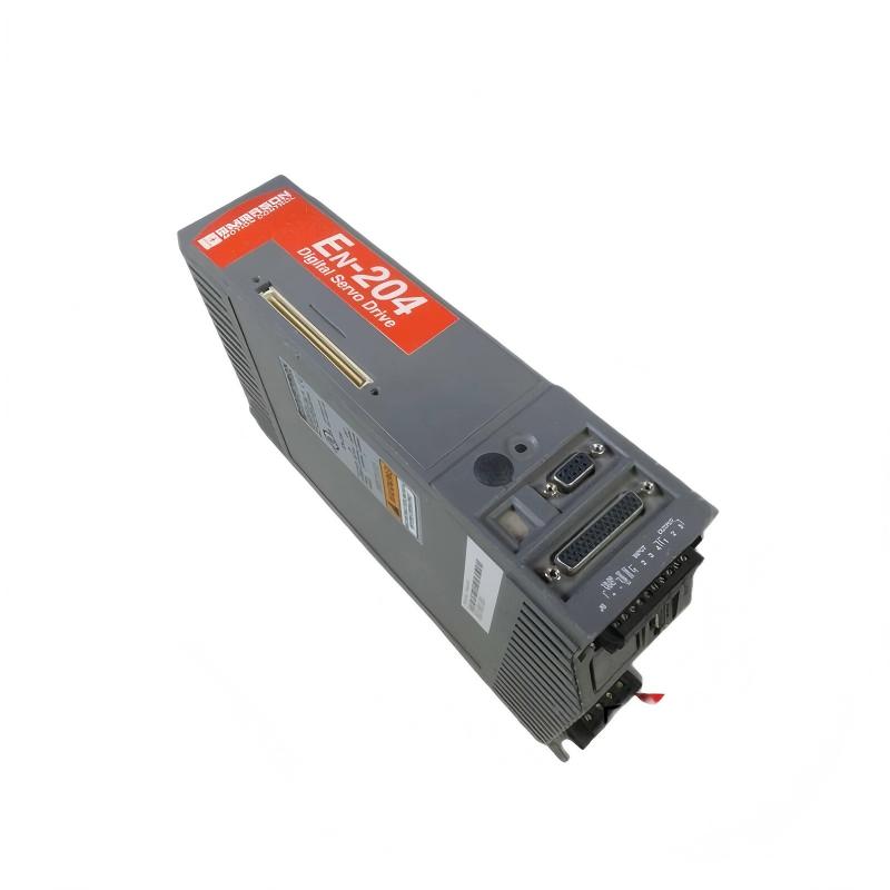
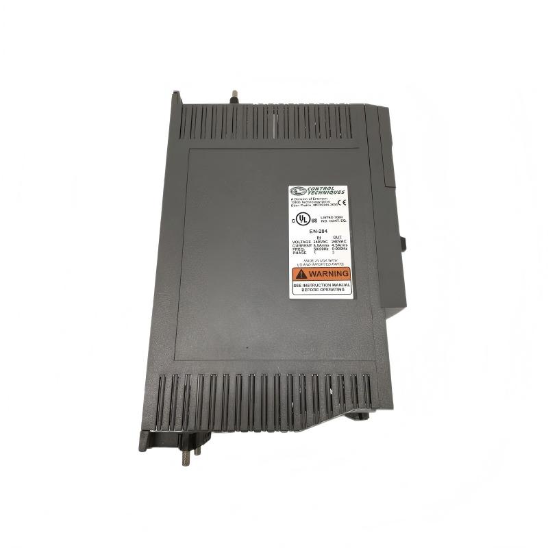
The EN-204-00-000 is part of the Emerson/Control Techniques EN Series of digital servo drives. The 240 VAC version is commonly specified with a 4.5 A continuous output rating and 9 A peak output capability.
Before installation, inspect the drive for physical damage and confirm that the nameplate information matches the replacement or original unit. The connected motor should also be checked against the intended drive configuration.
Keep the following items available:
Servo drive and compatible motor
AC power supply
Motor power cable
Feedback cable
Controller or motion interface
Proper grounding connections
Drive configuration software or parameter backup
Machine electrical drawings
Emerson EN-204 Servo Drive Wiring Considerations
The wiring arrangement should be checked as a complete system rather than terminal by terminal in isolation.
Motor power conductors should be routed separately from feedback and low-level control wiring where possible. Poor cable routing can introduce electrical noise into encoder signals and produce symptoms that initially look like a defective drive.
Pay particular attention to:
AC input connections
Motor phase connections
Protective earth
Feedback connector
Enable and control signals
Brake wiring where applicable
Controller command signals
Do not assume that matching wire colors guarantee correct feedback polarity or motor phasing. For an older machine, verify each conductor against the electrical drawing.
Emerson EN-204 Servo Drive Setup and System Configuration
The Setup process should begin with the motor and feedback information, followed by the required operating mode.
The EN Series supports motion functions involving pulse, velocity, and torque control. The selected operating mode must correspond with the controller and application architecture.
For a replacement EN-204, compare the original parameters whenever they are available. Important configuration points include motor selection, feedback type, command scaling, direction, current limits, acceleration, deceleration, and applicable machine limits.
A common commissioning mistake is to start tuning before confirming the basic configuration. If the wrong motor or feedback arrangement is selected, changing servo gains can hide the real problem rather than solve it.
Emerson EN-204 Servo Drive Commissioning Procedure
Commissioning should begin with the mechanical axis secured and the machine prevented from making an unexpected full-speed movement.
First verify that the drive powers correctly and that no immediate fault is displayed. Then confirm the controller enable signal and perform a low-speed jog or equivalent controlled motion command.
Observe the relationship between command and actual motor response.
If the commanded direction is positive but the axis moves negatively, stop the test and investigate the motor/feedback configuration. Do not repeatedly reverse wiring without understanding which signal is being changed.
During the first movement, monitor motor current, position response, abnormal noise, and mechanical resistance.
Emerson EN-204 Servo Drive Commissioning Validation
Once low-speed operation is stable, gradually test the normal acceleration and operating speed.
The EN-204 electrical capability should not be confused with the safe operating limit of the machine. Motor speed, load inertia, mechanical travel, feedback resolution, and application requirements must all be considered.
In one commissioning case, the motor initially responded incorrectly during the first enable test. Continuity checks showed that the field wiring was intact. The investigation then moved to the System Configuration and identified an incorrect motor selection. After correcting the configuration, the axis responded normally without replacing the drive.
This is a useful field lesson: when wiring checks pass but servo behavior is abnormal, configuration should be investigated before assuming internal hardware failure.
Emerson EN-204 Servo Drive Installation Guide Long-Tail Keywords
Relevant search phrases include:
Emerson EN-204-00-000 installation guide
Emerson EN-204 servo drive wiring
EN-204 servo drive setup
Emerson EN-204 commissioning procedure
EN-204 motor configuration
Emerson EN-204 feedback wiring
EN-204 servo drive system configuration
EN-204 replacement drive commissioning
A successful Installation Guide should end with stable low-speed operation, verified direction, correct feedback response, and controlled operation at the required machine speed.
Ready for installation and commissioning.

