Emerson EN-204 EN-204-00-000 Servo Drive Troubleshooting Guide
Time:2026-09-09 Browse: 20
Emerson EN-204-00-000 troubleshooting should begin by identifying when the fault occurs and what changes immediately before it. A drive that faults during acceleration requires a different Fault Diagnosis approach from one that cannot enable at all.
Emerson EN-204 Servo Drive Fault Symptoms
Field symptoms can include:
Servo drive will not enable
Motor stops during acceleration
Intermittent position errors
Motor runs briefly and then faults
Excessive current during movement
Unexpected direction
Faults occurring only after the machine warms up
Axis instability at higher speed
The timing of the fault is often more valuable than the fault symptom itself.
For example, a fault appearing only after acceleration begins suggests that load, current demand, feedback quality, or tuning should be examined. A fault present immediately after power-up points toward a different part of the system.
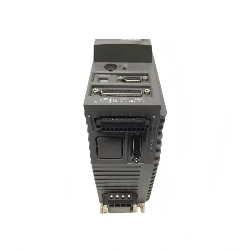
Emerson EN-204 Servo Drive Intermittent Position Fault Diagnosis
Consider a machine where the EN-204 operates normally during slow jogging but occasionally loses position at higher speed.
The first diagnostic question should be whether the commanded position and actual feedback remain consistent.
Inspect the feedback connector and cable before replacing the drive. Look for loose contacts, damaged shielding, excessive cable movement, and routing alongside high-current motor conductors.
A practical test is to compare behavior at several speeds:
Low speed: stable
Medium speed: occasional deviation
High speed: repeated position fault
This pattern increases suspicion of feedback integrity or electrical interference.
If the same fault occurs with a known-good feedback cable and the configuration has been verified, attention can then move toward the drive or motor feedback hardware.
Emerson EN-204 Servo Drive Overcurrent Fault Troubleshooting
An overcurrent fault should not automatically be classified as a failed output stage.
First determine whether the fault occurs immediately on enable or only when the motor begins accelerating.
An immediate fault calls for inspection of motor wiring, motor configuration, phase connections, and possible cable faults.
A fault that appears only under acceleration requires a broader investigation. Check mechanical resistance, load inertia, acceleration settings, and actual motor current.
The EN-204-00-000 is associated with approximately 4.5 A continuous and 9 A peak output capability. These figures provide useful context, but the correct operating current still depends on the connected motor and application.
A useful engineering distinction is:
Fault with motor disconnected → investigate drive-side electrical condition
Fault only with motor connected → inspect motor circuit and configuration
Fault only under mechanical load → investigate load and motion profile
This avoids replacing an expensive servo drive when the actual fault is mechanical.
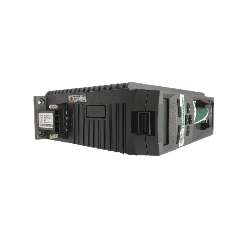
Emerson EN-204 Servo Drive No-Enable Fault Diagnosis
A no-enable condition is best approached as a logic-chain problem.
Check whether the drive has valid power and whether an active fault is preventing operation. Then trace the enable command from the controller toward the drive.
Check:
Controller output
Enable input
Safety/interlock conditions
Drive status
Configuration
External inhibit conditions
In one field case, the drive appeared to be defective because the motor would not respond after a replacement. Voltage measurements at the main supply were normal. The next diagnostic check showed that the controller enable condition was never becoming valid because an external interlock remained open.
The servo drive was therefore not the failed component.
Emerson EN-204 Servo Drive Unexpected Direction Fault
Unexpected direction is a particularly important commissioning and troubleshooting symptom because repeated testing can create a mechanical hazard.
Stop the machine and verify the command direction, motor configuration, and feedback interpretation.
Do not randomly exchange motor and encoder wires. A wiring change can create a second fault while leaving the original configuration problem unresolved.
For a replacement unit, compare the parameter set with the original machine configuration before attempting further motion.
Emerson EN-204 Servo Drive Repair Decision
Repair becomes reasonable only after external causes have been eliminated.
A practical Fault Diagnosis sequence is:
Power problem → correct the supply
Control problem → verify enable and command signals
Feedback problem → inspect cable, connector, and feedback device
Mechanical problem → inspect coupling, load, bearings, and travel mechanism
Configuration problem → restore correct System Configuration
Persistent internal fault → evaluate the drive for repair
This approach is particularly useful for older equipment where replacement units may require careful configuration matching.
Emerson EN-204 Servo Drive Troubleshooting Long-Tail Keywords
Common long-tail searches include:
Emerson EN-204-00-000 troubleshooting
Emerson EN-204 servo drive fault diagnosis
EN-204 servo drive not enabling
Emerson EN-204 overcurrent fault
EN-204 position error troubleshooting
Emerson EN-204 feedback fault
EN-204 servo drive repair
Emerson EN-204 configuration fault
EN-204 servo motor troubleshooting
The most effective Troubleshooting method is to separate the problem into power, control, feedback, motor, mechanical load, and System Configuration. That diagnostic logic provides a much more reliable path to repair than assuming the servo drive itself has failed.
Reliable troubleshooting starts with the fault pattern.

