Schneider TWDLMDA40DTK Modular Base Controller Installation Guide (Wiring & Commissioning)
Time:2026-09-10 Browse: 21
Schneider TWDLMDA40DTK installation should begin with the 24 VDC supply, I/O wiring, and Twido system configuration rather than software programming. The controller provides 24 DC inputs and 16 source transistor outputs, giving a total of 40 discrete I/O points, and supports up to seven I/O expansion modules.
Schneider TWDLMDA40DTK PLC Controller Installation Requirements
The TWDLMDA40DTK is a modular Twido PLC Controller designed for compact machine-control applications. Its rated supply is 24 VDC, with an allowable supply range of 20.4 to 26.4 VDC. The controller itself is rated at approximately 19 W under the specified operating conditions.
Before installation, confirm three things:
The control cabinet provides a stable 24 VDC supply.
The connected field devices are compatible with the 24 VDC discrete inputs.
The output devices are suitable for source-type transistor outputs.
A common field mistake is checking only whether the power supply is nominally 24 VDC. For commissioning, measure the voltage at the controller terminals rather than relying on the power-supply nameplate.
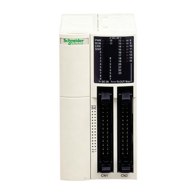
Schneider TWDLMDA40DTK Wiring and I/O Arrangement
The controller has 24 discrete inputs and 16 transistor source outputs. The inputs can accommodate sink or source logic, while the outputs are transistor source outputs. The base unit uses HE-10 connectors for I/O connections.
Keep input wiring physically separated from high-current motor, contactor, and inverter cables where possible. If an input is connected to a proximity sensor, photoelectric sensor, or pushbutton, verify the actual signal voltage at the PLC terminal with a multimeter.
For example, if a sensor is expected to produce 24 VDC but the measured PLC input is only 11–13 VDC, do not immediately change the System Configuration or replace the controller. Check the sensor supply, common connection, terminal wiring, and voltage drop first.
Schneider TWDLMDA40DTK System Configuration Before Power-Up
The hardware configuration should reflect the actual controller and connected expansion modules. The TWDLMDA40DTK supports up to seven I/O expansion modules, while two slots are available for specified options such as memory and real-time-clock functions.
A practical Setup check is to compare:
Configured I/O → Installed hardware → Actual field wiring
If these three do not agree, troubleshooting becomes much harder because a software address can appear correct while the physical signal is connected somewhere else.
When replacing an existing Twido controller, record the existing I/O assignment and expansion arrangement before removing the old unit. This simple record often saves more commissioning time than attempting to reconstruct the system from the program alone.
Schneider TWDLMDA40DTK Power-Up and Commissioning
During Setup / Commissioning, apply 24 VDC and observe the controller response before connecting the complete machine sequence.
Check the supply first. The documented allowable range is 20.4–26.4 VDC, and the controller has a specified tolerance for short power interruptions. Incorrect voltage or wiring can cause permanent damage even though reverse polarity protection is provided against operation under reverse polarity.
Once the controller is powered:
Confirm that the PLC enters its expected operating state.
Check the input status while manually activating selected field devices.
Test outputs with the machine in a safe condition.
Verify that each physical input corresponds to the intended program address.
Confirm the response of expansion modules before enabling automatic operation.
Do not test every output simultaneously on a live machine simply because the program appears correct. Commissioning should proceed from individual signals to functional groups.
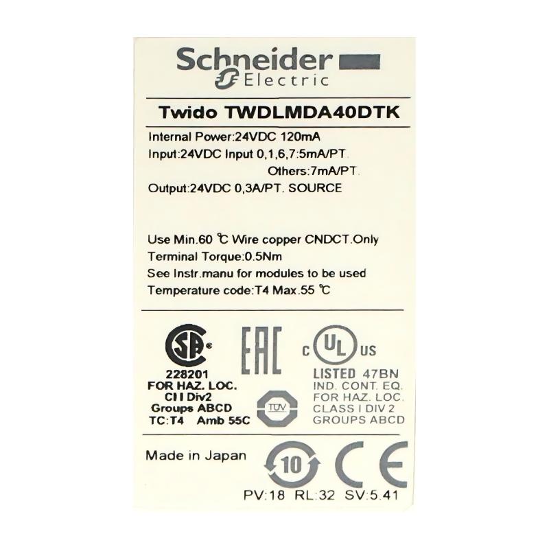
Schneider TWDLMDA40DTK Installation Faults to Watch For
One recurring installation problem is a common-reference error. The field sensor may have a correct 24 VDC supply, but the PLC input does not change because the sensor and controller do not share the intended reference.
Another issue is incorrect interpretation of source outputs. Because the TWDLMDA40DTK uses 16 transistor source outputs, the external load wiring must be designed around the output topology rather than copied from a relay-output PLC.
If an output appears active in the PLC program but the field actuator does not operate, measure the voltage at the output and then at the load. This immediately separates a PLC-side problem from a downstream wiring or actuator problem.
Schneider TWDLMDA40DTK Commissioning Example
In a representative machine commissioning case, several proximity switches were reported as “not detected” after the controller was powered up. The initial assumption was a faulty TWDLMDA40DTK input section.
The diagnostic process started with voltage measurement rather than replacing the controller. The sensor supply was approximately 24.1 VDC, but the signal measured at one PLC input remained below the expected switching level when the target was present.
The wiring was then traced back to the field terminal block. The sensor signal conductor was correct, but its reference connection had been landed on the wrong common terminal.
After correcting the reference wiring, the input changed state normally. No controller replacement was required.
This is typical of practical PLC Fault Diagnosis: verify the physical signal first, then the I/O channel, and only afterward consider a hardware failure.
Schneider TWDLMDA40DTK Installation Validation
A successful Installation Guide should finish with functional validation rather than simply confirming that the PLC powers on.
Verify:
24 VDC supply stability
All 24 digital input points required by the application
All 16 transistor outputs used by the machine
Expansion-module recognition
Correct I/O addresses
Safe manual output testing
Correct automatic sequence
Retention of the final System Configuration
The TWDLMDA40DTK is now discontinued, so engineers working on existing equipment should also document the controller configuration and available spare strategy. Schneider Electric lists M221-based alternatives, including TM221C40T and TM221M32TK depending on the required architecture. Migration should not be treated as a simple one-for-one hardware swap because I/O count, communication functions, and accessory compatibility can differ.
Long-Tail Keywords for Schneider TWDLMDA40DTK Installation
Schneider TWDLMDA40DTK Installation Guide, TWDLMDA40DTK PLC Controller setup, TWDLMDA40DTK 24VDC wiring, TWDLMDA40DTK commissioning procedure, TWDLMDA40DTK I/O configuration, Twido modular controller installation, TWDLMDA40DTK input wiring, TWDLMDA40DTK transistor output setup, and TWDLMDA40DTK System Configuration are relevant search terms for engineers maintaining legacy Twido control systems.

