Schneider TWDLMDA40DTK PLC Troubleshooting Guide (Fault Diagnosis)
Time:2026-09-10 Browse: 20
Schneider TWDLMDA40DTK faults should be diagnosed from the signal path outward: power supply, input or output circuit, controller logic, and then hardware. A PLC Controller showing an unexpected machine condition does not automatically indicate a failed CPU or I/O circuit. The TWDLMDA40DTK has 24 digital inputs and 16 source transistor outputs, so tracing the individual signal is usually faster than replacing the entire controller.
Schneider TWDLMDA40DTK PLC Fault Symptoms
A useful troubleshooting starting point is to classify the symptom.
Typical TWDLMDA40DTK problems include:
PLC powers up but an input never changes state
Output status changes in the program but the actuator remains off
Several I/O points disappear simultaneously
Machine sequence stops unexpectedly
Expansion I/O behaves differently after maintenance
Controller operates intermittently after cabinet work
The important distinction is whether the fault exists in one channel or across several channels.
One failed input suggests a field circuit or individual channel problem. Several inputs failing together suggests a common supply, reference, connector, or expansion issue.
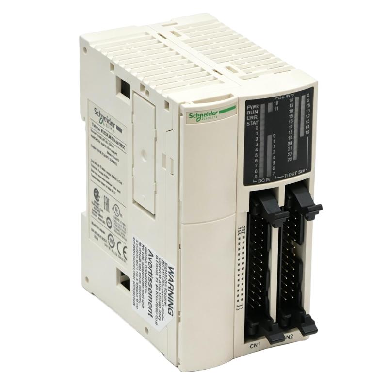
Schneider TWDLMDA40DTK Fault Diagnosis: Start With the Supply
The TWDLMDA40DTK operates from 24 VDC, with a specified input range of 20.4–26.4 VDC.
For intermittent faults, measure the voltage while the machine is actually operating. A static reading of 24.2 VDC with the machine stopped does not prove that the supply remains stable when contactors, valves, or other loads switch.
For example, a practical diagnostic sequence might produce:
PLC stopped: 24.3 VDC
Motor contactor energized: 21.0 VDC
PLC fault appears: 20.7 VDC
That pattern points toward a supply or distribution problem rather than an immediate controller failure.
This is why voltage should be measured at the PLC terminals, not only at the power-supply output.
Schneider TWDLMDA40DTK Input Fault Investigation
Suppose a proximity sensor is physically detecting a target, but the corresponding TWDLMDA40DTK input remains OFF.
Do not begin by replacing the PLC.
Follow the signal:
Sensor output → terminal block → cable → PLC connector → input channel → program address
If the sensor produces 24 VDC but the PLC terminal does not receive it, the fault is between the sensor and controller.
If 24 VDC reaches the input terminal but the PLC still shows no transition, the investigation moves toward the connector, channel, common reference, or controller hardware.
The TWDLMDA40DTK input characteristics include different current and filtering values across input groups, so field measurements should be interpreted against the appropriate channel specification rather than assuming every input behaves identically.
Schneider TWDLMDA40DTK Output Fault Diagnosis
A different failure pattern occurs when the PLC program indicates that an output is ON but the connected solenoid or contactor remains inactive.
The first question is:
Is the output electrically switching?
Measure the output circuit under the actual load condition. Since the TWDLMDA40DTK uses transistor source outputs, the external wiring must match the source-output arrangement.
If the PLC command is ON and the expected voltage is present at the controller but absent at the load, inspect the field wiring.
If the expected voltage is absent directly at the controller output, compare the affected channel with another known-good output under equivalent conditions.
This comparison is often more useful than immediately replacing the PLC Controller.
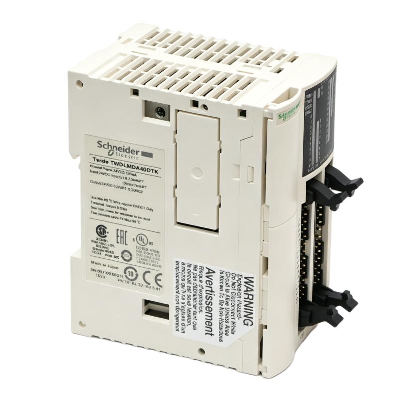
Schneider TWDLMDA40DTK Expansion Module Fault Pattern
A less obvious failure can appear after cabinet maintenance: the base controller continues running, but an expansion module is no longer behaving correctly.
The TWDLMDA40DTK supports up to seven I/O expansion modules.
If several signals associated with one expansion section fail at the same time, inspect the module connection and configuration before diagnosing multiple independent channel failures.
A useful engineering rule is:
One channel failed = investigate the channel.
One complete module failed = investigate the module connection and configuration.
Several modules failed = investigate the common system conditions.
This prevents a large amount of unnecessary component replacement.
Schneider TWDLMDA40DTK Troubleshooting Case: Intermittent Input Loss
In a representative field troubleshooting case, a machine operator reported that a limit switch occasionally disappeared from the PLC input monitor for less than a second.
The switch itself was replaced first, but the symptom remained.
The diagnostic focus then moved to signal measurement. The normal input voltage was approximately 24 VDC, but during machine vibration the signal briefly dropped to near 0 V.
A physical inspection found that the conductor was not firmly retained in the terminal block. The controller was not the root cause; vibration was intermittently opening the field circuit.
After correcting the termination and securing the wiring, the input remained stable during repeated machine cycles.
The important Fault Diagnosis lesson is that an intermittent PLC fault should be reproduced under the same mechanical and electrical conditions in which the machine normally fails.
Schneider TWDLMDA40DTK Repair Decision Process
Repair should be considered only after the external signal path has been eliminated as the cause.
A practical decision tree is:
Power abnormal?
→ Check 24 VDC supply and distribution.
Power stable but one input incorrect?
→ Trace sensor, reference, wiring, connector, and input channel.
Program output active but load inactive?
→ Measure the transistor output and inspect load wiring.
Multiple channels fail together?
→ Check common supply, connector, expansion interface, and System Configuration.
External circuits verified but controller behavior remains abnormal?
→ Consider controller hardware failure or replacement.
Because TWDLMDA40DTK is a discontinued Twido controller, repair decisions should also consider spare availability and migration planning. Schneider Electric identifies M221 controllers such as TM221M32TK and TM221C40T as replacement options, but compatibility must be checked against the existing application.
Schneider TWDLMDA40DTK Troubleshooting and System Configuration
Software should be treated as one part of Fault Diagnosis rather than the entire diagnostic process.
Compare the actual hardware with the System Configuration, then verify the physical I/O assignment against the application logic.
For an existing installation, preserve the original program and configuration before making changes. If a controller replacement becomes necessary, document communication accessories, expansion modules, memory options, and I/O assignments first.
Schneider's migration documentation shows that Twido and M221 feature sets are not identical, so migration can involve functional differences even when the replacement controller appears similar from an I/O-count perspective.
Schneider TWDLMDA40DTK Repair and Recovery Checks
After correcting a fault, do not stop when the PLC returns to RUN.
A proper recovery check should include:
Cold power-up
Repeated machine cycles
Input transition verification
Output-load verification
Expansion I/O verification
Communication checks where applicable
Confirmation that the original fault does not return
For intermittent problems, several hours of observation may be more valuable than a single successful restart.
Long-Tail Keywords for Schneider TWDLMDA40DTK Troubleshooting
Schneider TWDLMDA40DTK Troubleshooting Guide, TWDLMDA40DTK Fault Diagnosis, TWDLMDA40DTK PLC Controller fault, TWDLMDA40DTK input fault, TWDLMDA40DTK output troubleshooting, TWDLMDA40DTK 24VDC fault, TWDLMDA40DTK transistor output problem, TWDLMDA40DTK I/O troubleshooting, TWDLMDA40DTK repair, and Twido modular controller fault diagnosis are useful long-tail search terms for maintenance engineers working with legacy Schneider control systems.

