Allen-Bradley MPL-A520K-MK72AA Servo Motor Installation Guide (Setup & Commissioning)
Time:2026-09-17 Browse: 0
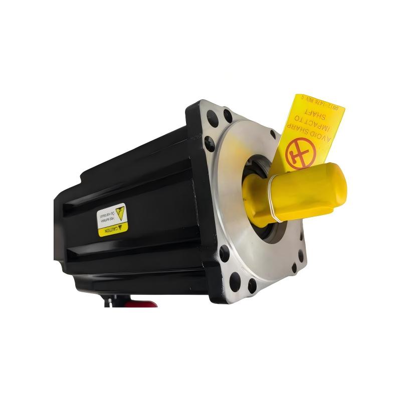
The Allen-Bradley MPL-A520K-MK72AA servo motor is a low-inertia MP-Series rotary servo motor designed for high-response motion applications. For installation, the critical points are not simply mounting the motor and connecting power: the motor feedback configuration, drive parameters, mechanical alignment, and System Configuration must all agree before commissioning. Available product information identifies the MPL-A520K-MK72AA as a 200 V-class motor with a 165 mm frame, 50.8 mm magnet stack, 4000 RPM rated speed, absolute multi-turn feedback, right-angle SpeedTec DIN connector, keyless shaft, and no brake.
Allen-Bradley MPL-A520K-MK72AA Servo Motor Installation Preparation
Before starting the installation, verify the exact nameplate information rather than assuming that another MPL motor has identical parameters. The MPL family includes different voltage classes, frame sizes, stack lengths, feedback configurations, and brake options.
For the MPL-A520K-MK72AA, the available specifications indicate:
Brand: Allen-Bradley
Series: MP-Series MPL
Type: Low-inertia servo motor
Model: MPL-A520K-MK72AA
Frame size: 165 mm
Magnet stack: 50.8 mm
Rated speed: 4000 RPM
Feedback: 1024 sin/cos absolute multi-turn encoder
Brake: None
Shaft: Keyless
Connector: SpeedTec DIN, right-angle, rotatable
Mounting: IEC metric flange with free mounting holes
Enclosure: IP50 minimum without shaft seal
The corresponding servo drive must be capable of operating with the motor's voltage class and feedback arrangement. Do not begin tuning until the motor identity in the drive configuration has been verified.
MPL-A520K-MK72AA Mechanical Installation and Alignment
The first practical check is mechanical, not electrical.
Mount the servo motor on a rigid machine surface and confirm that the mounting face is clean and free from burrs. Because the MPL-A520K-MK72AA uses a keyless shaft, coupling installation requires particular attention to clamping and alignment rather than relying on a shaft key to locate the coupling.
Check the following before tightening the mounting hardware:
Motor flange: The mounting surface should sit squarely against the machine.
Coupling: The coupling should not impose excessive radial or axial loading on the motor shaft.
Rotational alignment: Rotate the mechanical assembly manually where possible and check for abnormal resistance.
Cable routing: Keep power and feedback cables away from sharp edges and moving mechanisms.
A useful field check is to disconnect the motor from the load during initial commissioning when the machine design permits it. This separates motor/drive behavior from problems caused by a mechanically overloaded axis.
Allen-Bradley MPL-A520K-MK72AA Wiring and Feedback Setup
The electrical installation should be treated as two separate functions: motor power and feedback.
The motor power circuit supplies the three-phase motor, while the feedback connection provides the position and velocity information required by the motion controller and servo drive.
For the MPL-A520K-MK72AA, the feedback system uses an absolute multi-turn encoder. The right-angle SpeedTec DIN connector also affects cable routing, especially where the motor is mounted close to a machine frame.
Before applying power, inspect:
Motor power connector seating
Feedback connector seating
Cable insulation
Shielding and grounding arrangement
Connector orientation
Drive-to-motor compatibility
Encoder configuration in the drive
A common commissioning mistake is to correct the power wiring but overlook the feedback configuration. The motor can be electrically healthy and still fail to establish usable motion feedback.
MPL-A520K-MK72AA System Configuration Before Commissioning
The servo drive should contain the correct motor data before enabling the axis.
The configuration should correspond to the actual MPL-A520K-MK72AA rather than a visually similar MPL motor. Important parameters include motor model, voltage class, feedback type, feedback resolution, direction, and any application-specific limits.
If the drive software provides a motor database, select the exact catalog entry where available. If parameters must be entered manually, compare every value against the manufacturer's documentation and the motor nameplate.
This is also where the control system's axis configuration should be checked. A mismatch between commanded units and actual motor movement can produce apparently incorrect positioning even though the motor itself is functioning normally.
Allen-Bradley MPL-A520K-MK72AA Setup and Commissioning Checks
Initial commissioning should be performed at low speed and with conservative motion limits.
A practical sequence is:
Confirm the motor is mechanically secure.
Confirm the power and feedback connectors are fully seated.
Verify the motor model and feedback configuration.
Apply control power and check for drive faults.
Verify that encoder feedback is detected.
Test a small commanded movement.
Observe actual position and velocity feedback.
Increase speed gradually.
Connect or enable the full machine load only after basic axis behavior is stable.
Do not immediately run the axis at 4000 RPM simply because that is the motor's rated speed. The machine's mechanics, inertia ratio, load, acceleration, and application limits determine the appropriate operating conditions.
Real Commissioning Case: MPL Servo Axis Showing Position Error
In one commissioning case involving an MP-Series servo axis, the initial symptom was not a motor fault. The axis reached the commanded position but showed inconsistent positioning after repeated movements.
The engineer first checked the encoder feedback and found that the position signal remained stable with the motor unloaded. The next test introduced the mechanical coupling. The position error appeared only when the load was connected.
This changed the diagnostic direction.
Instead of replacing the motor, the engineer checked coupling alignment and mechanical backlash. The coupling installation was corrected, after which repeated positioning tests showed substantially more stable actual-position feedback.
The important lesson for an MPL-A520K-MK72AA Installation Guide is that commissioning should separate electrical, feedback, and mechanical variables. A position error does not automatically indicate an encoder failure.
Long-Tail Keywords for Allen-Bradley MPL-A520K-MK72AA Installation
The following search phrases naturally describe the engineering tasks covered by this procedure:
Allen-Bradley MPL-A520K-MK72AA installation guide
MPL-A520K-MK72AA servo motor setup
MPL-A520K-MK72AA commissioning procedure
Allen-Bradley MPL-A520K-MK72AA feedback setup
MPL-A520K-MK72AA servo motor wiring
Allen-Bradley MPL servo motor System Configuration
A successful installation is ultimately confirmed by stable feedback, predictable low-speed movement, correct direction, and repeatable positioning—not simply by the absence of an initial drive alarm.

