Emerson KJ2005X1-BA2 MX Controller Installation Guide (Setup & Commissioning)
Time:2026-09-18 Browse: 0
The Emerson KJ2005X1-BA2 MX Controller installation process should begin with carrier compatibility, power integrity, network connections, and controller identification—not with downloading a control strategy. In a DeltaV system, a controller that is mechanically installed but incorrectly seated, poorly connected, or mismatched with the system configuration can appear to be a software problem.
Emerson KJ2005X1-BA2 MX Controller Installation Planning
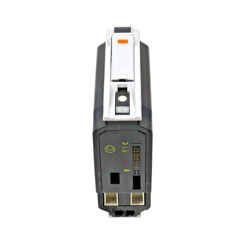
The KJ2005X1-BA2 is an M-series MX Controller designed for Emerson DeltaV distributed control systems. It is installed in the appropriate Power/Controller Carrier and communicates with the control network through dedicated network connections.
Before installation, inspect the carrier rather than assuming that the controller is the only component involved.
Check the carrier slot for:
Damaged or contaminated contacts
Loose mechanical hardware
Signs of overheating
Previous maintenance damage
Incorrect module position
The controller should slide into the carrier without excessive force. If significant resistance is encountered, stop and investigate the mechanical alignment.
From field experience, forcing an M-series module into position can turn a simple installation issue into a connector or carrier problem.

Emerson KJ2005X1-BA2 Power and Carrier Setup
The KJ2005X1-BA2 receives its operating power through the carrier. The documented local-bus requirement is +5 VDC, with current consumption up to 1.4 A. Typical power dissipation is approximately 5.0 W, with 7.0 W specified as the maximum.
This makes the carrier an important part of the Installation Guide.
After the controller is seated, verify that the Power indication behaves as expected. If there is no power indication, do not immediately conclude that the controller electronics have failed.
A practical commissioning check is:
Controller installed → carrier power verified → Power LED checked
If the first two conditions are correct but the controller remains unpowered, then the controller itself becomes a more relevant suspect.
Emerson KJ2005X1-BA2 MX Controller Network Wiring
The MX Controller provides primary and redundant control-network connections using 8-pin RJ-45 interfaces.
For systems using network redundancy, both paths should be checked independently. Do not assume that one healthy connection proves that the complete communication architecture is healthy.
During Setup, compare the physical connections against the existing System Configuration.
An engineer should confirm:
Primary network connection → correct
Redundant network connection → correct where applicable
Cable seating → secure
Network path → consistent with configuration
Controller identity → matches engineering records
If a controller is being replaced, photographing or recording the original cable arrangement before removal is a simple practice that can prevent an avoidable commissioning error.
Emerson KJ2005X1-BA2 System Configuration Before Commissioning
Hardware installation does not complete the job. The controller must also correspond with the intended DeltaV System Configuration.
Before downloading or modifying the control strategy, verify the controller's identity and status in the engineering environment.
The recommended engineering logic is:
Physical hardware
↓
Carrier power
↓
Network connectivity
↓
Controller status
↓
System Configuration
↓
Control strategy
This order is useful because it prevents a configuration problem from being confused with a physical installation problem.
Emerson KJ2005X1-BA2 MX Controller LED Validation
The controller's LEDs provide useful commissioning information.
The Power LED indicates that DC power is applied. The Error LED identifies an error condition. Active and Standby indications provide information about controller status, while the network indications provide information about primary and redundant communication.
During Setup, record the actual LED condition instead of simply writing "controller normal."
For example:
Power: ON
Error: OFF
Active: ON
Primary network: communicating
Secondary network: communicating
This creates a useful baseline for later Troubleshooting.
A controller that later develops a communication fault can then be compared against its original commissioning condition.
Emerson KJ2005X1-BA2 Commissioning Validation
A practical commissioning case illustrates why the sequence matters.
During one controller replacement, assume the new KJ2005X1-BA2 powers up normally but does not become available in the engineering environment. The first reaction may be to suspect the replacement controller.
Instead, the engineer checks the carrier, then the network connections. The secondary network is communicating, while the primary path is not.
That observation changes the diagnostic direction.
Rather than replacing the controller again, the engineer isolates the primary network path and checks its cable and network-side connection. Once the connection is corrected, controller communication returns.
The important lesson is that commissioning should follow evidence. A controller that powers correctly and communicates through one network path should not automatically be classified as defective because another path is unavailable.
Emerson KJ2005X1-BA2 Installation and Setup Fault Prevention
Several simple practices make future Fault Diagnosis easier.
Record the controller position and identification before installation. Keep the primary and redundant network paths clearly identified. Confirm the carrier condition before inserting a replacement module. Finally, record the LED state after successful commissioning.
The KJ2005X1-BA2 should also be operated within the specified environmental conditions. Excessive cabinet temperature, contamination, or poor airflow can create intermittent problems that are difficult to reproduce during bench testing.
For a maintenance team, the best Installation Guide is therefore not just a mounting procedure. It is a baseline that makes later Troubleshooting faster.
Emerson KJ2005X1-BA2 MX Controller Long-Tail Search Terms
Engineers looking for specific installation information may use the following long-tail queries:
Emerson KJ2005X1-BA2 MX Controller Installation Guide
Emerson KJ2005X1-BA2 Setup and Commissioning
KJ2005X1-BA2 DeltaV MX Controller installation
Emerson KJ2005X1-BA2 control network setup
KJ2005X1-BA2 System Configuration commissioning
These terms cover the practical workflow from physical installation through final DeltaV commissioning.

