ABB V18345-1004210001 Valve Positioner Installation Guide: Setup and Commissioning
Time:2026-09-21 Browse: 0
ABB V18345-1004210001 valve positioner installation starts with correct actuator matching, feedback alignment, pneumatic supply, and 4–20 mA loop verification. This ABB electro-pneumatic positioner uses a two-wire 4–20 mA input and supports HART communication, while published specifications identify linear and rotary actuator mounting options.
ABB V18345-1004210001 Valve Positioner Installation Preparation
Before installing the ABB V18345-1004210001, confirm the actuator type, valve travel, fail action, mounting arrangement, and pneumatic requirements. The positioner can be used with linear and rotary actuators, with mounting arrangements associated with DIN/IEC 534, NAMUR, and VDI/VDE 3845 applications.
For a replacement installation, record the original positioner settings before removing the old unit. Pay particular attention to the direction of valve travel and the relationship between the input signal and valve position.
The instrument-air system should also be checked before commissioning. Published specifications identify a 1.4–6 bar supply range and instrument air according to DIN/ISO 8573-1 Class 3.
Clean and stable air is especially important when the valve is expected to make small positioning corrections.
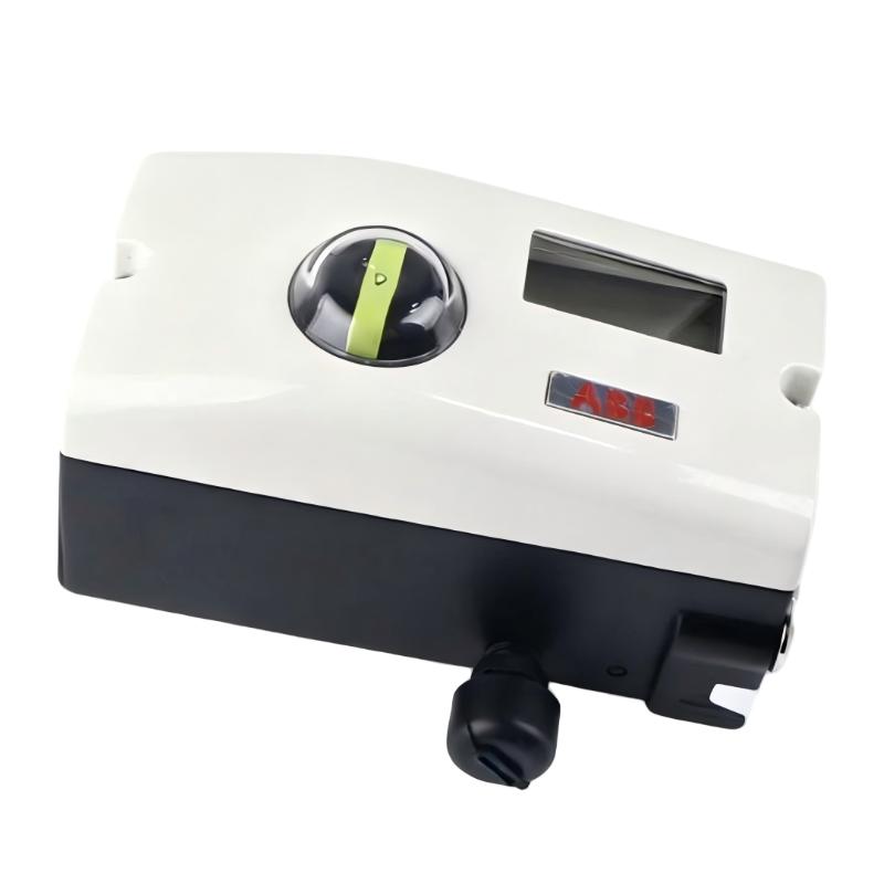
ABB V18345-1004210001 Mechanical Mounting and Feedback
Mount the positioner firmly to the actuator using the appropriate mechanical arrangement. The feedback mechanism must follow actuator movement throughout the complete operating range.
A useful field check is to move the actuator toward its minimum, middle, and maximum positions while watching the feedback linkage.
The linkage should move continuously without binding.
There should also be no excessive mechanical play. Loose feedback connections can create a situation in which the positioner repeatedly corrects an apparent position error that is actually caused by mechanical movement.
Do not attempt to compensate for poor mechanical alignment by changing electronic parameters.
If the feedback mechanism reaches its mechanical limit before the actuator reaches full travel, correct the mounting position first.
ABB V18345-1004210001 4–20 mA Wiring Setup
The ABB V18345-1004210001 uses a two-wire nominal 4–20 mA input. The available specifications also identify HART Protocol 5.1 communication for configuration and diagnostics.
Before connecting the loop, verify the polarity and the analog-output configuration of the PLC or DCS.
After energizing the loop, measure the actual current at the field device.
A practical check is to command approximately 4 mA, 12 mA, and 20 mA and observe the positioner's response.
These values should not automatically be interpreted as exact 0%, 50%, and 100% valve travel because the configured range, split range, valve characteristic, and actuator direction can affect the relationship between signal and travel.
The model's published specifications indicate configurable split range from 20% to 100% of the nominal input range.
ABB V18345-1004210001 Setup and Commissioning Procedure
The Setup / Commissioning process should be performed only after the mechanical and pneumatic installation has been checked.
First verify that the positioner is correctly powered.
Then change the input command gradually and observe the actuator.
Check whether increasing the command produces the intended direction of valve movement.
If the valve travels in the opposite direction, correct the configuration before proceeding with further calibration.
Next, test several intermediate positions instead of checking only the two endpoints.
For example, command approximately 25%, 50%, 75%, and 100% travel. Then return toward the lower end.
During this test, observe whether the valve response is smooth or whether it shows hesitation, overshoot, sudden movement, or excessive delay.
These observations are valuable for later Troubleshooting because they establish the normal operating pattern of the installed valve positioner.
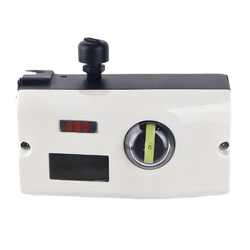
ABB V18345-1004210001 System Configuration Verification
The System Configuration should be checked before the valve is released to automatic process control.
Verify the input range, actuator direction, travel configuration, valve characteristic, and relevant diagnostic parameters.
If HART communication is being used, compare the field configuration with the PLC or DCS engineering configuration.
A common commissioning error is to configure the analog output in the control system for one operating range while the positioner is configured differently.
The result can look like an incorrect calibration even though both devices are operating according to their individual settings.
Recording the configuration before commissioning also makes later Fault Diagnosis much easier.
ABB V18345-1004210001 Commissioning Validation
A valve positioner should not be considered commissioned simply because it completes one full stroke.
Repeat the movement several times.
Watch both directions of travel.
Pay attention to whether the valve stops consistently at the same positions.
In one commissioning case, an ABB positioner repeatedly stopped short of the expected upper valve position. The initial suspicion was an incorrect calibration value. The engineer first checked the 4–20 mA signal and found it stable. The investigation then moved to the mechanical assembly, where the feedback linkage was found to be reaching its mechanical limit before the actuator completed its stroke.
After correcting the linkage, the valve completed its expected travel without replacing the positioner.
This is a useful field diagnostic principle: prove the mechanical feedback path before assuming that an electronic calibration parameter is wrong.
ABB V18345-1004210001 Installation Guide Long-Tail Keywords
This Installation Guide covers ABB V18345-1004210001 valve positioner installation, ABB V18345-1004210001 setup, ABB V18345-1004210001 commissioning, ABB V18345-1004210001 4–20 mA wiring, ABB V18345-1004210001 HART setup, ABB V18345-1004210001 valve positioner calibration, and ABB V18345-1004210001 System Configuration.

