ABB V18345-1004210001 Valve Positioner Troubleshooting Guide: Fault Diagnosis for Slow Valve Respons
Time:2026-09-21 Browse: 0
ABB V18345-1004210001 troubleshooting for slow valve response should begin by separating an electrical command problem from a pneumatic or mechanical response problem. When the 4–20 mA command changes normally but the valve takes several seconds to respond, the positioner itself should not be blamed until the air circuit and actuator have been checked.
ABB V18345-1004210001 Slow Response Fault Symptoms
A typical field complaint is that the control valve responds correctly but too slowly after a command change.
For example, the DCS changes the command from approximately 8 mA to 16 mA, but the valve takes several seconds to reach the new position.
The first question is whether the ABB V18345-1004210001 receives the command immediately.
If the measured positioner input changes from 8 mA to approximately 16 mA without delay, the PLC or DCS output is unlikely to be the first fault location.
The investigation should then move toward the pneumatic output, actuator, valve stem, and mechanical feedback assembly.
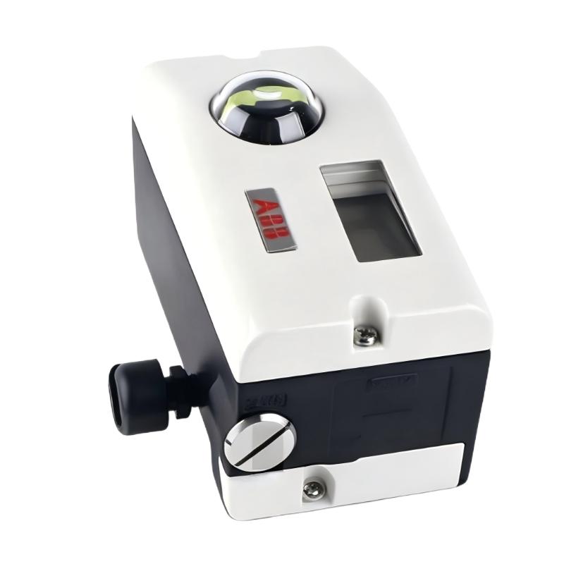
ABB V18345-1004210001 Fault Diagnosis Through the Signal Path
A useful Fault Diagnosis method is to divide the complete control loop into four sections:
Control-system output → positioner input → pneumatic actuator response → valve mechanical movement.
Measure the 4–20 mA signal directly at the positioner.
Do not rely exclusively on the PLC display.
If the PLC shows 16 mA but only 12 mA reaches the field device, the problem exists upstream of the positioner.
If approximately 16 mA reaches the V18345-1004210001 and the positioner responds, the electrical section is probably not the primary cause.
This simple separation can save considerable maintenance time.
ABB V18345-1004210001 Pneumatic Troubleshooting
The next inspection point is instrument air.
Measure the air supply while the valve is actually moving.
A pressure reading taken while the valve is stationary may appear normal even when the supply becomes unstable during movement.
Check for:
Restricted tubing
Loose pneumatic fittings
Contaminated filters
Pressure-regulator problems
Air leakage
Insufficient actuator capacity
The published specification for this model identifies a pneumatic supply range of approximately 1.4–6 bar, with the actual operating requirement determined by the actuator and valve assembly.
If the positioner output changes quickly but the actuator responds slowly, pneumatic restriction becomes a stronger possibility.
ABB V18345-1004210001 Valve and Actuator Inspection
Do not overlook valve friction.
A control valve can develop increasing stem resistance because of packing problems, corrosion, process deposits, or mechanical wear.
One useful observation is to compare movement in both directions.
If opening is slow while closing is relatively fast, or vice versa, investigate the actuator and valve mechanics rather than assuming that the electronic positioner has failed.
The feedback linkage should also be checked.
A loose linkage can create delayed position feedback. The positioner then sees an apparent position error and continues correcting the actuator.
This can produce a cycle of movement that looks like poor tuning.
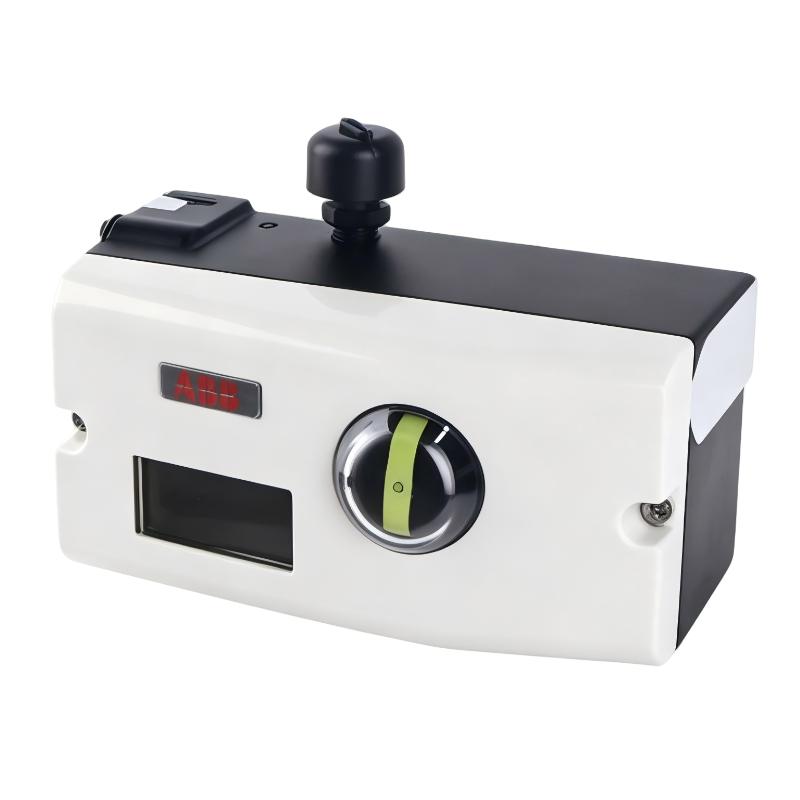
ABB V18345-1004210001 Real Field Fault Investigation
In one field troubleshooting case, a valve was reported to have a response delay of approximately 6 seconds after a command change.
The maintenance team initially suspected the positioner because the valve had previously operated normally.
The first measurement showed that the DCS command changed from approximately 8 mA to 16 mA immediately.
The same signal was measured at the positioner input.
The technician then monitored pneumatic behavior during the movement and found that the actuator supply pressure dropped noticeably when the valve was commanded to move.
The pneumatic tubing was subsequently inspected and a restriction was found close to the actuator.
After the restriction was removed, the valve response became significantly faster.
The important part of the Fault Diagnosis was not simply finding a blocked tube. It was proving that the electrical command reached the positioner correctly before moving the investigation into the pneumatic section.
ABB V18345-1004210001 HART Diagnostic Approach
Where HART communication is available, use it to inspect configuration and diagnostic information before changing parameters. The V18345-1004210001 is documented with HART communication capability.
Record the current System Configuration before making changes.
Check the configured input range, actuator direction, travel parameters, and relevant diagnostic information.
Avoid changing multiple parameters during the same test.
For example, if a technician changes the dead band, valve characteristic, actuator direction, and travel limits simultaneously, it becomes difficult to determine which change affected the behavior.
A controlled troubleshooting process should change one factor at a time.
ABB V18345-1004210001 Electrical Versus Mechanical Fault Diagnosis
The diagnostic decision can be simplified by comparing three observations.
If the 4–20 mA signal is incorrect at the positioner, investigate the PLC/DCS analog output, wiring, loop resistance, and power supply.
If the input signal is correct but the positioner does not produce the expected pneumatic response, investigate the positioner configuration and internal operation.
If the positioner produces the expected pneumatic response but the valve moves slowly, investigate the actuator, air supply, valve stem, packing, and mechanical linkage.
This approach reduces unnecessary positioner replacement.
A functioning positioner should not be replaced simply because the final control valve response is poor.
ABB V18345-1004210001 Repair Verification
After correcting the suspected fault, repeat the original operating condition.
Do not stop after confirming that the valve moves once.
Command several different positions and observe the response in both directions.
For a slow-response fault, compare the response time before and after repair.
For example, if the valve previously required approximately 6 seconds to move to the commanded position and now reaches the same position in approximately 2 seconds under the same conditions, the repair has stronger evidence behind it.
Also verify that the valve does not develop a new problem at another travel point.
A proper Repair process ends with repeatable operation, not simply with the disappearance of one alarm.
ABB V18345-1004210001 Troubleshooting Long-Tail Keywords
This Troubleshooting Guide covers ABB V18345-1004210001 troubleshooting, ABB V18345-1004210001 Fault Diagnosis, ABB V18345-1004210001 slow valve response, ABB V18345-1004210001 pneumatic troubleshooting, ABB V18345-1004210001 4–20 mA troubleshooting, ABB V18345-1004210001 HART diagnostics, ABB V18345-1004210001 valve positioner repair, and ABB V18345-1004210001 actuator troubleshooting.

