Schneider 140CPS42400 Power Supply Module Installation and Commissioning Guide
Time:2026-10-28 Browse: 6
Schneider 140CPS42400 Power Supply Installation Requirements
The Schneider 140CPS42400 power supply module requires a suitable DC supply and a correctly configured Modicon Quantum rack to deliver stable 5.1 V DC power to the PLC backplane. This redundant power supply accepts a nominal 48–60 V DC input, with published technical documentation specifying an input operating range of 40–72 V DC. Verifying the applicable hardware specifications, wiring polarity, and rack compatibility before startup helps prevent commissioning failures.
The 140CPS42400 is designed for standalone or redundant operation, depending on the system configuration. Its backplane output is rated at 5.1 V DC and up to 8 A under the specified operating conditions. These characteristics make it important to assess the rack load and installation temperature before putting the PLC into service.
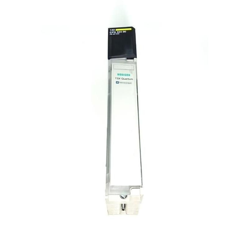
Schneider 140CPS42400 Technical Data and Preparation
| Parameter | Specification |
|---|---|
| Product type | Redundant power supply module |
| Automation platform | Modicon Quantum |
| Nominal input voltage | 48–60 V DC |
| Documented input operating range | 40–72 V DC |
| Backplane output voltage | 5.1 V DC |
| Output current | Up to 8 A, subject to operating conditions |
| Maximum input current | 1.3 A at 48 V DC in the hardware reference |
| Input interruption tolerance | 13 ms at 48 V DC |
| Recommended external fuse | 2 A medium time-lag |
| Power indication | Green PWR OK LED |
| Alarm output | Normally closed relay contact |
| Weight | Approximately 0.65 kg |
Before installation, confirm that the DC supply can handle the module's input demand and startup inrush current. The manufacturer's hardware reference lists an inrush current of 25 A at 48 V DC, so the upstream supply and protective devices should be selected with this characteristic in mind.
Inspect the module, field wiring connector, and rack for damage. Check that the selected power supply is compatible with the intended standalone or redundant arrangement.
Schneider 140CPS42400 Wiring and Rack Installation
The 140CPS42400 uses a seven-point field wiring connector. The documented terminal layout includes the alarm relay, 48 V DC negative and positive inputs, and connections associated with an optional hold-up capacitor.
Disconnect the DC source and verify that the circuit is de-energized before handling the connector. Connect the positive and negative conductors according to the manufacturer's wiring diagram, and use the specified protective fuse and appropriate conductor sizes.
The alarm relay is available on terminals 1 and 2. Confirm its contact rating and the receiving circuit requirements before integrating it into the PLC alarm system.
If additional input interruption tolerance is required, the hardware documentation describes an optional 80 V DC electrolytic capacitor connected to the designated capacitor terminals. Its capacitance must be selected using the manufacturer's timing chart; do not install an arbitrary capacitor.
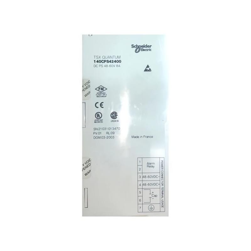
Schneider 140CPS42400 Setup and Commissioning Checks
After completing the wiring inspection, restore power according to the site's approved startup procedure. Observe the green PWR OK indicator and confirm that the processor and installed modules initialize normally.
During commissioning, measure the DC input at the designated test point. For example, a measured 48.5 V DC would fall within the documented 40–72 V DC operating range. This is an illustrative measurement, not a report from a specific installation.
If the PWR OK LED remains off, inspect the input voltage, polarity, fuse, connector, and rack seating before concluding that the module is defective.
For redundant operation, verify the installed power supply combination against the Modicon Quantum compatibility matrix. Confirm that the arrangement supports the intended load and that the system's power-failure alarm behaves correctly.
Schneider 140CPS42400 System Configuration Validation
A complete Setup / Commissioning procedure should include both a startup check and a functional test under representative load conditions.
Confirm that the processor remains operational, the power supply indicator stays normal, and the alarm relay changes state as expected when tested using the manufacturer's approved procedure.
For a redundant configuration, validate the system's response to a power supply fault only under an authorized test plan. Do not disconnect live power modules or deliberately interrupt a running control system without assessing process and personnel safety.
Record the input voltage, rack arrangement, module identification, indicator status, and test results. This information provides a baseline for subsequent maintenance and Fault Diagnosis.
Schneider 140CPS42400 Installation Guide: Long-Tail Keywords
Relevant search phrases include Schneider 140CPS42400 installation guide, 140CPS42400 48 V DC power supply wiring, Modicon Quantum redundant power supply commissioning, Schneider 140CPS42400 PWR OK LED, and 140CPS42400 rack configuration requirements.