Foxboro P0973CN Expansion Backplane Installation Guide for FCP270 Systems
Time:2026-10-29 Browse: 2
Foxboro P0973CN Expansion Backplane Installation Requirements
The Foxboro P0973CN Expansion Backplane is a four-position vertical mounting baseplate designed for compatible Foxboro control-system configurations, including redundant FCP270 Field Control Processors and FEM100 Fieldbus Expansion Modules. Successful installation depends on correct module placement, secure DIN-rail mounting, verified power connections, and proper integration with the existing System Configuration.
Unlike a standalone PLC Controller or I/O Module, the P0973CN provides the physical and electrical interconnection structure for the associated control hardware. Its installation therefore affects both mechanical stability and the communication paths between installed components. The Foxboro Series 200 baseplate documentation identifies the P0973CN as a four-position baseplate for two FCP270 processors and two FEM100 modules.
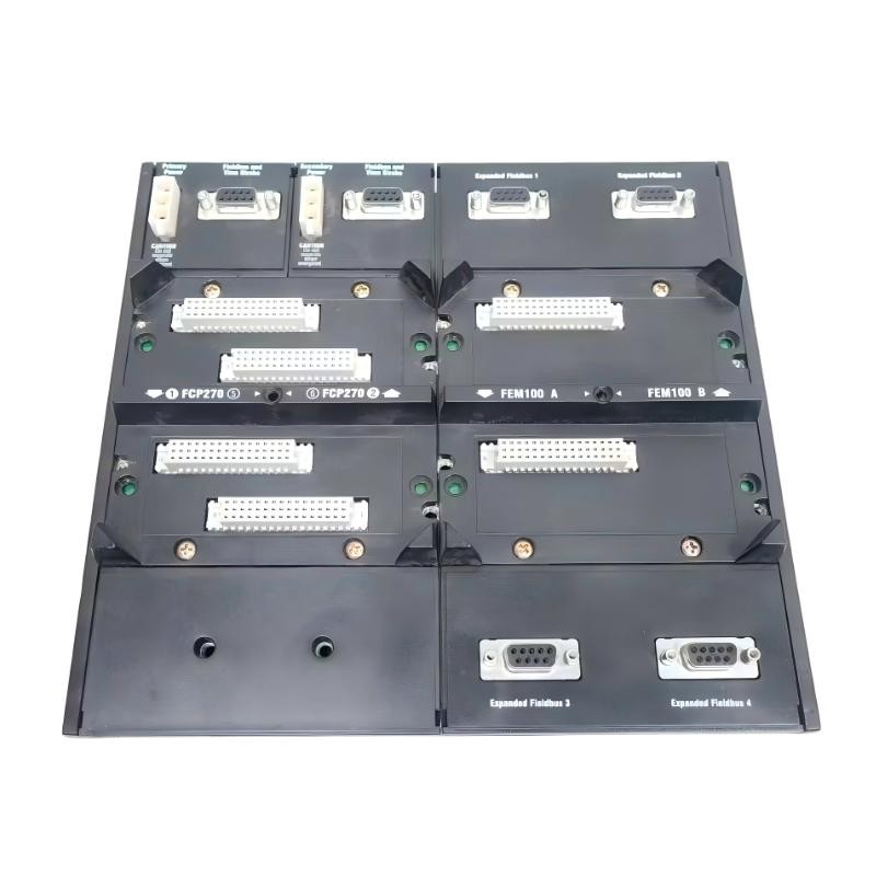
Planning the Foxboro P0973CN Backplane Installation
Before starting work, review the cabinet layout, approved system drawings, processor redundancy arrangement, and required expansion-bus connections. Confirm the exact part number and hardware revision rather than relying on the appearance of an existing assembly.
The P0973CN is intended for a specific controller and expansion-module arrangement. Engineers should verify that the selected processor, FEM100 modules, associated power supplies, and interconnection accessories match the intended system design.
Particular attention should be given to three areas:
Mechanical support: Confirm that the vertical DIN rail is securely mounted and suitable for the installed assembly.
Electrical interfaces: Inspect power connectors, module contacts, and bus connections for contamination, damage, or looseness.
Configuration compatibility: Check module placement and redundancy requirements against the approved Foxboro documentation.
If the installation is part of a live-system expansion, establish whether the existing architecture supports in-service addition. The manufacturer's documentation describes online addition of certain Series 200 baseplates when a redundant bus is provided; this capability must not be assumed for every configuration. <Cite refs={["turn304796search12","turn304796search13"]}/>
Mounting and Connecting the Foxboro P0973CN Expansion Backplane
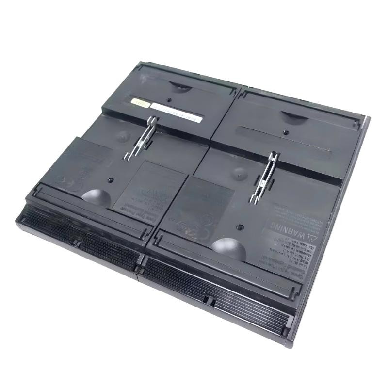
The P0973CN uses a vertical mounting arrangement. Secure the designated DIN rail and position the backplane according to the manufacturer's mechanical instructions. Check that the assembly is aligned correctly and that adjacent equipment does not obstruct module insertion or connector access.
Once the mounting arrangement has been verified, inspect the designated module positions before installing the FCP270 and FEM100 hardware. Confirm each module's orientation and seating requirements from the applicable product documentation.
The installation checks should include:
| Installation area | Engineering verification |
|---|---|
| DIN-rail mounting | Rail and backplane are mechanically secure |
| Module positions | FCP270 and FEM100 placement matches the approved layout |
| Power connections | Primary and secondary supply arrangements match the system design |
| Expansion bus | Required A/B bus connections are correctly routed |
| Redundancy | Both intended paths are connected and independently verifiable |
| Cabinet wiring | Cable identification and routing agree with system drawings |
Do not insert or remove modules, or alter power and communication wiring, unless the documented maintenance procedure permits the action. A redundant architecture does not eliminate the risks associated with disturbing shared connections.
Foxboro P0973CN Setup and Commissioning Validation
Commissioning should establish that the physical assembly, electrical supply, and controller configuration agree with one another. Begin with the equipment de-energized where required by the approved procedure, then complete the mechanical and wiring inspections before restoring power.
After startup, review processor and expansion-module status indications using the correct manufacturer documentation. Verify that the expected FCP270 processors and FEM100 modules are recognized and that the configured expansion-bus paths report healthy status.
For redundant installations, check the A/B communication paths independently. A normal controller indication does not, by itself, prove that both paths are operational.
A commissioning record should capture:
Installed part numbers and hardware revisions.
Module positions and power-source identification.
Controller and FEM100 diagnostic states.
Expansion-bus communication status.
Configuration discrepancies and corrective actions.
Final acceptance results under the site's approved test procedure.
Do not apply assumed voltage tolerances, bus timing limits, or acceptance thresholds. Use the specifications for the actual installed revision and associated equipment.
Foxboro P0973CN Installation Case: Expansion Module Not Recognized
Consider a representative commissioning situation in which the backplane is mounted correctly, but one FEM100 module is not recognized after startup.
An experienced engineer would first distinguish a mechanical seating problem from a power or communication fault. The module's local status, connector condition, assigned position, and system diagnostic messages should be reviewed before any hardware is replaced.
If the module is correctly seated and powered, the next checks should focus on the relevant configuration and bus connections. If other installed modules are recognized normally, that observation narrows the investigation toward the affected module, its interface, or its specific configuration. If several modules show related faults, a shared connection or supply becomes a stronger candidate.
This is an illustrative field-engineering scenario, not a verified customer incident. The diagnosis should be documented only after the actual installation provides supporting evidence.
Foxboro P0973CN Installation Guide: Long-Tail Technical Checks
This Installation Guide addresses common questions about Foxboro P0973CN Expansion Backplane mounting, FCP270 and FEM100 integration, setup and commissioning, redundant-bus verification, and System Configuration checks after hardware installation.
The central commissioning principle is to verify the complete assembly rather than treating the backplane as an isolated component. Mechanical integrity, correct module placement, power distribution, and communication-path validation together provide the evidence needed for a reliable installation.