Foxboro P0916ND Base-to-Base Cable Installation Guide (HDLC Fieldbus Setup)
Time:2026-11-05 Browse: 1
Understanding the Foxboro P0916ND Cable Application
The Foxboro P0916ND is a 0.25 m (10 in) HDLC shielded twisted-pair module fieldbus cable used in Foxboro I/O subsystem installations. Correct cable selection, connector engagement, and routing are essential for maintaining reliable communication between compatible system components.
Unlike conventional field wiring, an HDLC communication cable carries data between subsystem components. Its installation therefore requires attention to connector integrity, cable routing, shielding, and the specific hardware configuration.
The P0916ND should be treated as a communication interconnect rather than a general-purpose signal or power cable.
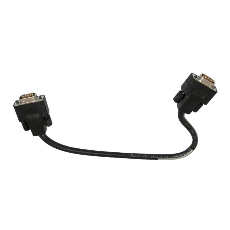
Foxboro P0916ND Installation Requirements
Before beginning the Installation Guide procedure, verify the following conditions:
Confirm that P0916ND is the specified cable for the intended Foxboro subsystem.
Check the hardware documentation for compatible base and extension components.
Verify that both connection points use the correct mating interfaces.
Inspect the cable jacket and connectors for cracks, deformation, or contamination.
Confirm that the 0.25 m cable length is suitable for the installed equipment arrangement.
The Foxboro cable family also includes P0916MZ, P0916NC, P0916NB, and P0916NA, which have different cable lengths. These alternatives should not be substituted without checking the applicable system requirements.
Cable Connection and Physical Installation
During installation, first place the relevant equipment in the approved maintenance condition. Follow the plant isolation procedure before disconnecting or reconnecting communication hardware.
Position the P0916ND between its designated connection points without introducing excessive tension. The short cable length makes connector alignment particularly important when adjacent modules or base assemblies are closely spaced.
Pay attention to these installation details:
Keep the cable away from sharp cabinet edges.
Avoid tight bends immediately behind the connectors.
Do not pull the cable by its conductors or connector housing.
Ensure that connectors are fully seated and mechanically secured.
Maintain separation from high-noise power conductors where the cabinet design permits.
A cable that appears mechanically connected may still have an intermittent electrical contact. Connector engagement should therefore be checked rather than assumed.
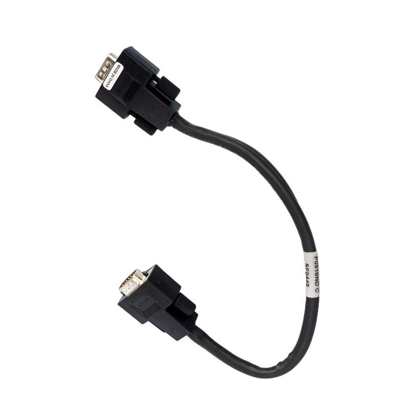
Foxboro P0916ND Setup and Commissioning
After the physical installation, restore the equipment according to the approved startup sequence.
The commissioning process should focus on communication stability rather than simply confirming that the cable is connected.
Check the following conditions:
Verify that the connected subsystem components are recognized by the system.
Review available communication status indicators.
Check for HDLC communication errors or unexpected link interruptions.
Confirm that the associated I/O hardware operates normally.
Monitor communication status during the initial operating period.
If the system reports communication errors, inspect the cable connections before changing System Configuration parameters.
Installation Validation and Field Considerations
A useful commissioning practice is to establish a baseline before returning the subsystem to normal operation.
For example, record the initial communication status, active diagnostic messages, and module recognition state. Compare these observations after installing the P0916ND.
In a representative commissioning scenario, an intermittent communication alarm should not immediately be attributed to a defective cable. Connector seating, incorrect interconnection, and hardware compatibility should be investigated first.
The installation can be considered satisfactory when the connected equipment is correctly recognized, communication remains stable, and no new cable-related diagnostic alarms appear.
Foxboro P0916ND Installation Guide: Long-Tail Technical Topics
Engineers searching for Foxboro P0916ND installation information may also need guidance on:
Foxboro P0916ND 0.25 m HDLC cable installation
P0916ND shielded twisted-pair communication connection
Foxboro module fieldbus cable compatibility
Foxboro I/O subsystem communication setup
HDLC fieldbus cable connector inspection
Foxboro P0916ND commissioning and communication validation
These considerations help distinguish a cable installation issue from a subsystem configuration or hardware problem.
Technical Reference
The Foxboro B0700DP.C Intrinsically Safe I/O Subsystem User's Guide identifies P0916ND as a 0.25 m (10 in) HDLC shielded twisted-pair module fieldbus cable.
Cable selection and installation should follow the documentation applicable to the actual Foxboro subsystem and hardware revision.