Honeywell TC-RPSC03 Experion LS Redundant Power Cable Installation Guide
Time:2026-06-11 Browse: 6
Honeywell TC-RPSC03 redundant power cable installation issues are most often caused by incorrect chassis adaptor pairing or reversed connector orientation rather than actual cable failure. In Experion LS Series-A redundant power systems, the TC-RPSC03 plays a critical role in linking the redundant power supply modules to the chassis adaptor, ensuring uninterrupted 24 VDC backplane power during supply switching events.
Honeywell TC-RPSC03 Redundant Power Cable Role in Experion LS System
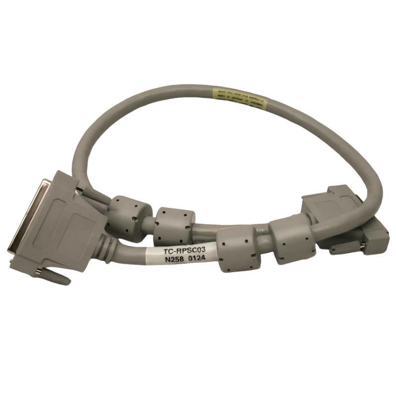
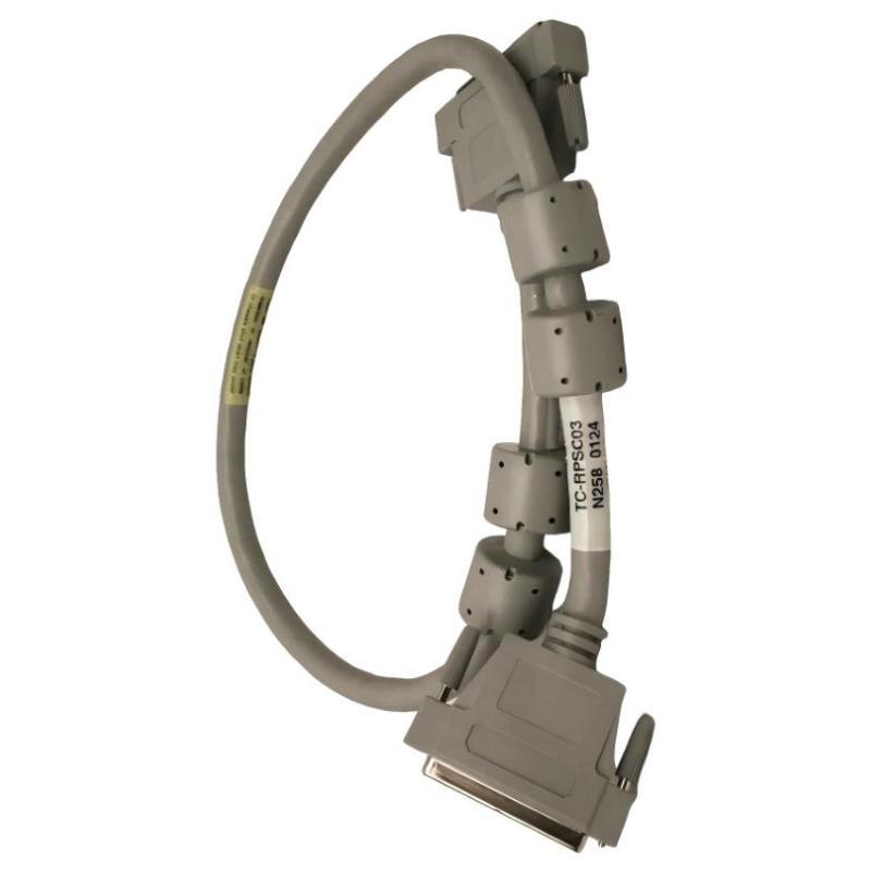
The TC-RPSC03 is a 1-meter redundant power interconnect cable used in older Experion LS Series-A redundant architectures. It connects:
Redundant power supply module (TC-RPDXX1 / TC-RPCXX1)
Chassis adaptor module (TC-RPSCA1 legacy system)
Unlike newer TC-PRSC04 cables, TC-RPSC03 is part of the legacy redundant power design, meaning correct wiring is essential to avoid startup instability or power sharing imbalance.
System Preparation Before Installation
Before installing Honeywell TC-RPSC03 in any PLC / Module / Power system:
Verify redundant power supply version (legacy vs new RPSCA2 system)
Confirm chassis type compatibility (Series-A only)
Ensure both power supplies are de-energized
Inspect connector pins for oxidation or mechanical stress
In one commissioning case in a petrochemical control room, we found intermittent boot failures caused not by PLC logic but by a slightly bent pin inside the TC-RPSC03 connector—resulting in unstable backplane voltage during module initialization.
Wiring & Physical Installation Process
The installation is straightforward but highly sensitive to connector alignment:
Align female connectors on TC-RPSC03 with power supply output ports
Connect both redundant supplies symmetrically (PS1 and PS2 must mirror each other)
Route cables with minimum bending radius (>30 mm recommended)
Secure cable strain relief to avoid vibration fatigue
Verify secure seating on chassis adaptor side (RPSCA1 interface)
Engineering note:
Avoid mounting redundant supplies directly above each other. Field tests show internal ambient temperature can exceed 60°C within 1 inch, reducing cable and connector life.
Commissioning & System Validation
After installation, perform structured commissioning:
Measure DC output stability at backplane: 24 VDC ±2%
Verify load sharing between redundant supplies
Check LED redundancy indicators on chassis adaptor
Simulate single power supply failure
In one Experion LS setup, we intentionally removed PS1 under load. Voltage drop remained within 0.3 V fluctuation, confirming correct TC-RPSC03 redundancy behavior.
Common Installation Mistakes
Mixing TC-RPSC03 with TC-PRSC04 system architecture
Incorrect chassis adaptor generation (RPSCA1 vs RPSCA2)
Loose connector locking causing intermittent faults
Ignoring cable routing heat exposure
Summary
Proper installation of the Honeywell TC-RPSC03 redundant power cable ensures stable PLC Controller operation and prevents backplane power interruption. Most commissioning issues originate from mechanical installation errors rather than electrical failure, making physical inspection a critical step in every Setup / Commissioning workflow.

