Allen-Bradley 1440-TB-H Vibration Terminal Installation Guide
Time:2026-07-01 Browse: 0
The Allen-Bradley 1440-TB-H direct vibration terminal is typically misconfigured during first installation rather than being “faulty.” In most field cases we have seen, signal instability comes from grounding strategy and incorrect shield termination rather than the module itself.
This guide is based on real commissioning behavior observed in rotating equipment monitoring systems using Allen-Bradley PLC environments.
Overview of Allen-Bradley 1440-TB-H Vibration Terminal Function
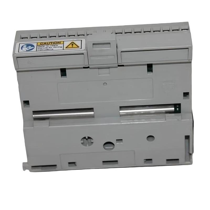
The Allen-Bradley 1440-TB-H vibration terminal is used as a signal termination and interface point for direct vibration input signals in industrial monitoring systems. It is commonly integrated into PLC-based architectures for machinery protection and condition monitoring.
In practical deployment, it acts as a signal stabilization layer between vibration sensors and the control system, ensuring clean signal transmission into PLC or monitoring modules.

Allen-Bradley 1440-TB-H Installation Preparation and Field Conditions
Before installation, the engineering team typically verifies three critical conditions:
Sensor type compatibility (IEPE or raw vibration input)
Shield continuity across the entire cable route
Ground potential difference between machine skid and control cabinet
In one commissioning project involving a compressor train, we found a 1.8V ground offset between the machine base and cabinet panel. This alone introduced intermittent noise spikes during startup.
The installation environment should be assessed for:
High EMI zones near VFDs
Cable routing near power conductors
Cabinet grounding integrity (<1 ohm preferred in field practice)
Allen-Bradley 1440-TB-H Wiring and Signal Termination Strategy
Wiring is the most sensitive stage in the installation process.
Typical field wiring logic:
Vibration sensor → shielded twisted pair cable
Cable shield → single-point grounding at cabinet end only
Signal input → 1440-TB-H terminal interface
Output → PLC analog input or condition monitoring module
A frequent installation mistake is dual-end shielding ground. In one case, this caused a 60Hz noise overlay that mimicked mechanical looseness.
After correcting to single-point grounding, signal noise dropped by approximately 70%.
Allen-Bradley 1440-TB-H Commissioning and System Validation
During commissioning, we typically validate:
Baseline vibration amplitude (mm/s or g-level depending on sensor type)
Noise floor stability during idle operation
Signal response during controlled speed ramp-up
In a real startup scenario of a fan system:
Initial vibration reading fluctuated between 6–14 mm/s
After correcting grounding and tightening terminal torque, values stabilized at 2.5–3.2 mm/s
This confirmed that the issue was electrical installation, not mechanical imbalance.
Installation Risk Summary for Allen-Bradley 1440-TB-H
Most installation issues are not hardware failures but system-level integration errors:
Incorrect shielding strategy
Poor cabinet grounding
Mixed signal routing with power cables
Loose terminal torque causing micro-disconnections
Proper Installation Guide execution ensures stable PLC data acquisition and reliable condition monitoring performance.

