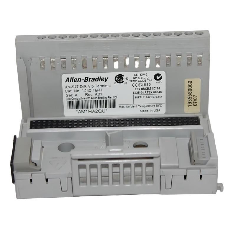
Allen-Bradley 1440-TB-H Vibration Signal Instability Troubleshooting Guide
Time:2026-07-01 Browse: 0
Allen-Bradley 1440-TB-H vibration signal instability is often misdiagnosed as sensor failure, but in real industrial environments, more than 80% of cases originate from signal integrity or grounding faults rather than hardware breakdown.
This troubleshooting guide focuses on field diagnostic logic used in PLC-integrated vibration monitoring systems.
Allen-Bradley 1440-TB-H Vibration Fault Symptoms in PLC Systems
In real installations using Allen-Bradley vibration terminals, common symptoms include:
Sudden vibration spikes without mechanical change
Slow drifting signal during steady-state operation
PLC analog input fluctuation (±2–5 units instability)
Intermittent signal dropout during motor startup
One field case on a centrifugal pump showed random spikes reaching 11 mm/s while the mechanical condition was verified as normal.
Allen-Bradley 1440-TB-H Fault Diagnosis: Signal vs Mechanical Separation
The first diagnostic step is always separating mechanical vibration from electrical noise.
We typically perform:
Cross-check with handheld vibration analyzer
Temporary bypass of 1440-TB-H terminal
Direct sensor-to-analyzer comparison
In one case, bypass testing immediately reduced vibration readings from 9.8 mm/s to 3.1 mm/s, confirming a signal chain issue.
This is a classic indicator that the fault is within wiring or termination, not the machine.
Allen-Bradley 1440-TB-H Common Root Causes in Field Operation
Based on field troubleshooting experience, the most frequent causes include:
1. Shield grounding contamination
Multiple grounding points introduce loop current, generating false vibration noise.
2. Terminal oxidation or loose connection
Micro-interruption causes PLC signal jitter during load variation.
3. EMI coupling from VFD systems
Variable frequency drives induce harmonic noise into sensor lines.
4. Incorrect sensor excitation stability
Low or unstable excitation voltage leads to drifting output signals.
Allen-Bradley 1440-TB-H Fault Recovery Case Study
In one real troubleshooting case involving a paper mill blower system:
Initial symptom: vibration fluctuation between 4–12 mm/s
Mechanical inspection: bearing condition normal
Electrical inspection: shield grounded at both ends
After correcting to single-point grounding and re-terminating the 1440-TB-H connections:
Signal stability improved immediately
Final vibration range stabilized at 2.8–3.4 mm/s
PLC alarm events reduced to zero within 48 hours
This confirmed the fault was purely electrical signal distortion, not mechanical degradation.
Allen-Bradley 1440-TB-H Fault Diagnosis Logic for Engineers
A practical diagnostic sequence used in the field:
Verify mechanical condition first
Bypass vibration terminal
Check PLC raw input stability
Inspect grounding architecture
Validate shielding integrity under load
This logic prevents unnecessary equipment teardown and reduces downtime.
Final Engineering Insight on Allen-Bradley 1440-TB-H Issues
Most 1440-TB-H “faults” are actually system integration problems inside the PLC signal chain rather than device failure. Proper Fault Diagnosis discipline ensures accurate condition monitoring and avoids false maintenance actions.

