ABB ACS355-03E-01A2-4 3ABD0000058242 Variable Frequency Drive Installation Guide
Time:2026-07-07 Browse: 20
ABB ACS355-03E-01A2-4 VFD Installation Guide for Industrial Motor Applications
ABB ACS355-03E-01A2-4 installation issues are commonly caused by incorrect motor data setup, improper wiring practices, or incomplete commissioning procedures instead of a defective variable frequency drive. The ABB ACS355-03E-01A2-4 (Order Code: 3ABD0000058242) is a compact AC drive designed for machine automation applications where accurate motor control, reliable speed regulation, and stable communication with control systems are required.
In practical installations, the ABB ACS355-03E-01A2-4 should be treated as part of the complete motor control system. The final performance depends not only on the drive itself but also on motor selection, cable routing, grounding quality, and System Configuration inside the PLC Controller environment.
ABB ACS355-03E-01A2-4 Installation Preparation and Engineering Assessment
Before mounting the ABB ACS355-03E-01A2-4, field engineers usually start by checking how the drive will operate inside the machine rather than simply replacing the existing inverter.
The first evaluation normally focuses on the relationship between the drive and motor:
Whether the motor rated current matches the drive output capability
Whether the application requires constant torque or variable torque control
Whether the PLC Controller sends analog speed reference, digital commands, or fieldbus signals
Whether the installation environment allows sufficient cooling airflow
During one machine upgrade project, an ABB ACS355-03E-01A2-4 was installed to replace an aging inverter on a small packaging conveyor. The motor nameplate showed a rated current of 0.85 A, while the previous drive configuration contained parameters from a larger 1.5 A motor. The motor could run, but acceleration was unstable and current peaks reached 1.32 A.
After entering the correct motor voltage, current, frequency, and speed values into the ABB ACS355-03E-01A2-4 System Configuration, the startup current reduced to 0.94 A and the conveyor operated normally.
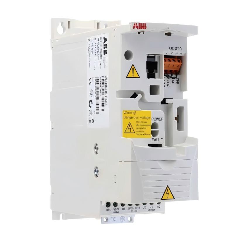
ABB ACS355-03E-01A2-4 Wiring Installation and Motor Connection Practice
The wiring stage of the ABB ACS355-03E-01A2-4 Installation Guide requires attention to both power wiring and control signal separation.
The incoming three-phase supply is connected to the drive input terminals, while the motor cable is connected to the U/V/W output terminals. Protective earth connection quality is especially important because poor grounding can create unstable reference signals and communication interference.
In industrial environments, one frequent installation mistake is placing motor cables together with low-voltage PLC communication cables. Although the drive may start correctly, electromagnetic interference can later cause unstable analog feedback or unexpected control reactions.
During a commissioning activity on a machine line, engineers observed that the speed reference signal fluctuated between 7.8 V and 8.4 V even though the PLC output remained constant at 8 V. After separating the motor cable routing and improving cable shielding, the analog signal variation dropped below 0.1 V.
ABB ACS355-03E-01A2-4 Setup and Commissioning Procedure
The Setup and Commissioning phase determines whether the ABB ACS355-03E-01A2-4 will deliver stable motor performance.
After power connection, engineers normally configure:
Motor rated voltage
Motor rated current
Motor nominal frequency
Motor speed
Acceleration and deceleration characteristics
Control command source
The commissioning process should begin with a low-speed motor test before applying full machine load.
In one field commissioning case, the ABB ACS355-03E-01A2-4 was installed on a pump application. The drive started correctly, but the motor vibration increased during acceleration. Diagnostic checks showed that the acceleration ramp was too short for the mechanical inertia of the pump.
The acceleration time was adjusted from 1.5 seconds to 6 seconds. After modification, the motor current became stable and vibration levels returned to normal operating conditions.
ABB ACS355-03E-01A2-4 Commissioning Validation and System Testing
A completed ABB ACS355-03E-01A2-4 installation is confirmed through operational testing rather than only successful power-up.
Engineers normally verify:
Correct motor rotation direction
Stable frequency output
Current response under load
PLC Controller command accuracy
Emergency stop and restart behavior
A final commissioning record should include measured operating values because these values become useful references for future Fault Diagnosis.
For example, recording a normal running current of 0.88 A allows maintenance engineers to quickly identify abnormal conditions if the current later increases to 1.3 A without mechanical changes.
ABB ACS355-03E-01A2-4 Long Tail Installation Guide Keywords
Industrial users searching for ABB ACS355-03E-01A2-4 Installation Guide, ABB ACS355-03E-01A2-4 wiring setup, ABB ACS355-03E-01A2-4 commissioning procedure, ABB ACS355-03E-01A2-4 parameter configuration, and ABB ACS355-03E-01A2-4 VFD integration usually require practical installation experience rather than general product information.

