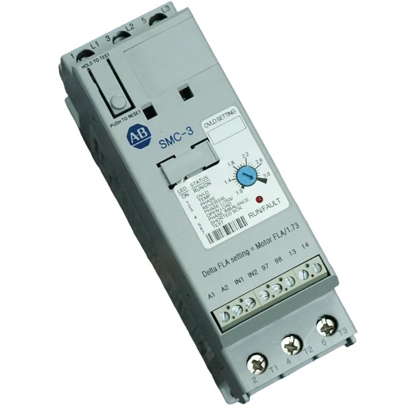
Allen Bradley 150-C3NBR SMC-3 Smart Motor Controller Installation Guide
Time:2026-07-08 Browse: 23
Overview of Allen Bradley 150-C3NBR SMC-3 Smart Motor Controller Installation
The Allen Bradley 150-C3NBR SMC-3 Smart Motor Controller installation process requires correct power wiring, motor connection, and parameter configuration to achieve reliable soft starting performance. In industrial applications, incorrect phase connection, unsuitable overload settings, or improper control wiring are common reasons for unsuccessful commissioning.
The Allen Bradley 150-C3NBR is a solid-state motor controller designed to reduce mechanical stress during motor startup by controlling voltage applied to three-phase induction motors. This Installation Guide explains practical setup methods, commissioning checks, and field considerations for integrating this PLC-controlled motor starter module into industrial systems.
General Information About Allen Bradley 150-C3NBR SMC-3 Controller
The Allen Bradley 150-C3NBR SMC-3 Smart Motor Controller belongs to the SMC-3 family developed by Rockwell Automation under the Allen Bradley brand. The product is manufactured with industrial motor control requirements in mind and is widely applied in pumps, conveyors, fans, compressors, and processing equipment.
Brand: Allen Bradley
Country of Origin: United States
Unlike traditional electromagnetic starters, the 150-C3NBR uses solid-state control technology to provide controlled acceleration and reduced inrush current. It is commonly installed alongside PLC Controller systems where digital start/stop commands and fault feedback monitoring are required.
Preparation Before Allen Bradley 150-C3NBR SMC-3 Installation
Before mounting the Smart Motor Controller, engineers should confirm several system conditions:
Motor full-load current must match the controller rating.
Supply voltage should correspond with the motor application.
Control voltage must match the selected control circuit.
Cabinet ventilation should prevent excessive heat accumulation.
During one commissioning project involving a 15 kW pump motor, the initial installation failed because the enclosure temperature exceeded the recommended operating range. The measured cabinet temperature reached 58°C during continuous operation, causing thermal protection activation. After improving airflow and relocating heat-producing components, the controller operated normally.
Allen Bradley 150-C3NBR Power Wiring and Motor Connection
The power connection of the Allen Bradley 150-C3NBR requires careful attention to line and load terminals.
Typical wiring checks include:
Verify incoming three-phase power at line terminals.
Connect motor leads to the load terminals.
Confirm grounding continuity.
Check contactor bypass wiring if used.
Before energizing the system, engineers normally measure:
Phase-to-phase voltage balance
Ground resistance
Motor insulation condition
A voltage imbalance above approximately 2% may create additional motor heating and should be corrected before commissioning.
Allen Bradley 150-C3NBR Control Circuit Setup and System Configuration
The control circuit determines how the SMC-3 receives operation commands from external devices.
Common configuration points include:
Start/stop push buttons
PLC output signals
Auxiliary relay feedback
Fault indication contacts
In PLC applications, the controller output should be tested using diagnostic logic before connecting the motor. A simple commissioning method is to verify:
PLC output ON → SMC-3 receives command → Run indicator activates → Motor accelerates smoothly
This sequence helps separate PLC programming issues from motor controller wiring problems.
Allen Bradley 150-C3NBR SMC-3 Commissioning Validation
After installation, commissioning should focus on actual motor behavior rather than only indicator status.
Field engineers typically check:
Starting current reduction
Acceleration time
Motor vibration
Controller temperature
Fault history
In one field commissioning case, a conveyor motor originally showed a starting current peak of 420 A. After adjusting the SMC-3 start parameters, the current peak was reduced to approximately 260 A, reducing mechanical impact on the gearbox.
Long-Tail Keywords for Allen Bradley 150-C3NBR Installation Guide
This Allen Bradley 150-C3NBR Installation Guide covers:
Allen Bradley 150-C3NBR SMC-3 Smart Motor Controller setup
Allen Bradley motor controller wiring procedure
SMC-3 commissioning and configuration
PLC Controller integration with soft starters
Industrial motor startup troubleshooting preparation
Reliable installation improves motor protection performance and extends equipment service life.
New In Stock

