Schneider TM5NEIP1K EtherNet/IP Fieldbus Interface Module Installation Guide
Time:2026-08-06 Browse: 8
Schneider TM5NEIP1K EtherNet/IP Module Installation Overview
Schneider TM5NEIP1K EtherNet/IP Fieldbus Interface Module installation problems are usually related to incorrect network configuration, power distribution wiring, or I/O island assembly rather than module hardware failure. In industrial applications, successful commissioning depends on correct integration between the PLC Controller, EtherNet/IP scanner, TM5 remote I/O architecture, and System Configuration settings.
The TM5NEIP1K works as the communication gateway between the EtherNet/IP network and TM5 distributed I/O modules. During installation, engineers must verify mechanical assembly, 24 VDC power supply, Ethernet communication parameters, and controller mapping before machine startup.
Schneider TM5NEIP1K Fieldbus Module Installation Preparation
Before mounting the Schneider TM5NEIP1K EtherNet/IP Fieldbus Interface Module, the complete hardware chain should be checked.
A typical installation requires:
TM5NEIP1K EtherNet/IP interface assembly
TM5 bus base connection
Interface Power Distribution Module
TM5 I/O expansion modules
24 VDC control power
Industrial Ethernet connection
The most common commissioning mistake observed in the field is installing the communication module correctly but forgetting to verify the power distribution path of the remote I/O island.
In one machine upgrade project, the TM5NEIP1K was mechanically installed correctly, but the remote I/O modules remained offline. The diagnostic process showed that the Ethernet link was active while the I/O power section measured only 18.6 VDC instead of the expected 24 VDC. After correcting the power supply wiring, all modules entered normal communication status.
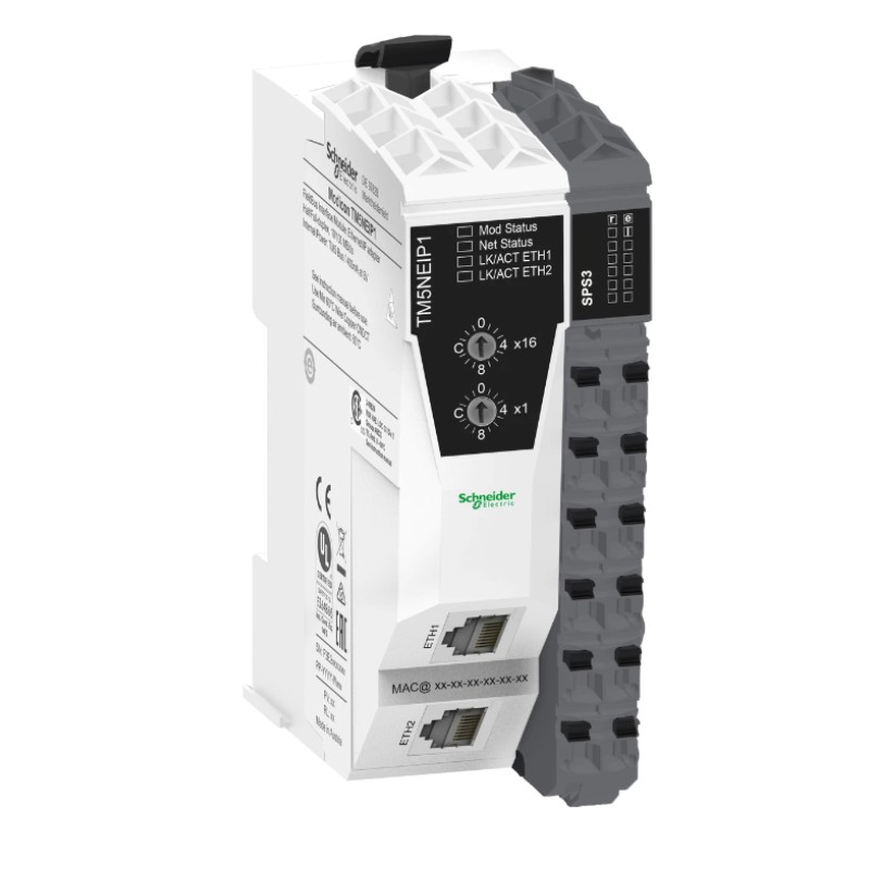
Schneider TM5NEIP1K Ethernet/IP Wiring and Network Setup
EtherNet/IP communication reliability depends heavily on network planning.
During Schneider TM5NEIP1K Setup, engineers should check:
Ethernet cable shielding
Switch port configuration
IP address assignment
Network segmentation
PLC Controller scanner settings
A practical commissioning method is to validate communication in layers:
Confirm physical Ethernet link.
Check IP address response.
Verify EtherNet/IP device recognition.
Confirm I/O assembly mapping.
Test real field signals.
For example, during a packaging machine commissioning case, the PLC could detect the TM5NEIP1K device but failed to update input data. The network diagnostics showed communication latency below 5 ms, but the I/O assembly configuration did not match the PLC project. After correcting the System Configuration parameters, the input refresh became stable.
Schneider TM5NEIP1K PLC Controller Configuration and Commissioning
The final stage of the Installation Guide is PLC Controller integration.
The commissioning engineer should verify:
Device name assignment
IP configuration
EtherNet/IP scanner connection
Input/output data size
Module addressing
Application logic response
A recommended validation sequence:
Communication Test
Check whether the PLC recognizes the TM5NEIP1K as an active EtherNet/IP adapter.
Signal Test
Force selected outputs and confirm physical device response.
System Test
Run the machine cycle and monitor communication stability.
Field experience shows that a stable network does not always indicate a correct configuration. A module can remain online while incorrect I/O mapping creates delayed machine responses or unexpected alarms.
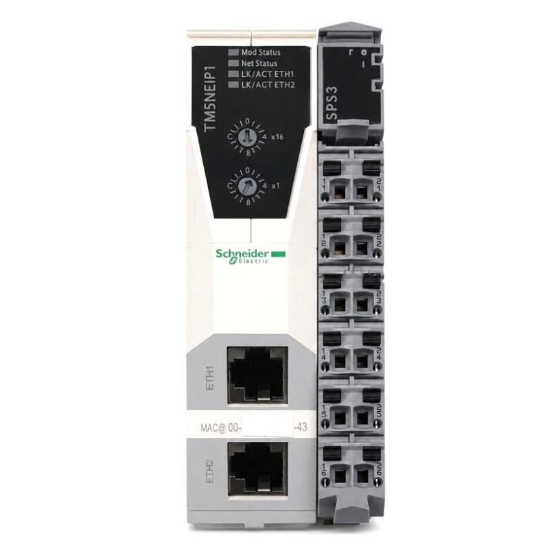
Schneider TM5NEIP1K Installation Guide Long-Tail Keyword Summary
This Schneider TM5NEIP1K EtherNet/IP Fieldbus Interface Module Installation Guide focuses on:
Schneider TM5NEIP1K PLC Controller integration
EtherNet/IP Module Setup and Commissioning
TM5NEIP1K network configuration
Industrial remote I/O installation
PLC communication validation
Fieldbus Module System Configuration
Proper installation reduces communication downtime and improves long-term machine reliability.

